This thread has been locked.

If you have a related question, please click the "Ask a related question" button in the top right corner. The newly created question will be automatically linked to this question.

DS90UB928Q-Q1: 928 OLDI output

Part Number: DS90UB928Q-Q1

dear,expert:

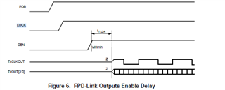
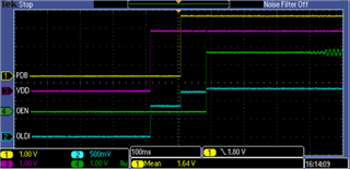
accodrding to 928 datasheet ,when VDD33 and VDDIO power up,pdb and oen power up,oldi(TxOUT(3:0),TxCLKOUT) output from 0V to normally,but in fact test ,when VDD33 and VDDIO power up ,the PDB and OEN not power up, this time test the OLDI output above 1V DC level, when PDB power up,the OLDI output 1.2V DC level;

1.so I want to know whether this phenomenon is normal;

2.Can I set the OLDI output to 0V by set the registers ?

  • Hi Zongtao,

    What is the serializer that you are trying to connect? Does this happen on one board or multiple boards?

    Aaron

  • hello Aaron:

    Thank you for reply.this happen on multiple boards, we connect the video source serializer is 981 ,and connect other video source which serializer is 948 , have same phenomenon.

  • Hello Zongtao,

    Is the 928 output connected to the panel? If so are you sure that the OLDI is not getting pulled up by the panel side? Can you check by disconnecting the 928 from the panel? Because our understanding is that before PDB = H, the OLDI outputs should be High-Z 

    Best Regards,

    Casey 

  • hello Casey:

    thank you for reply; at my testing,928 output disconnect to the display; so  can you test at you side if it is convenient for you?

    our other diaplay project  which use 948 also have the same phenomenon,they close the OLDI output by set the register;

  • Hi Zongtao,

    I can verify on the bench for you using 981 -> 928 with 720P. I will get back with you by 8/13.

    Aaron

  • Hi Zongtao,

    Just want to let you know I am currently working on this, and I need more time to look into this.

    Aaron

  • waiting for your reply...

  • Hi Zongtao,

    I was able to get the 981 and 928 to lock, but I do not have the 720p display. I will reach out to IT if they have any spare one. I will keep you posted by tomorrow.

    Aaron

  • thank you for support ~from my side,I`m not connect to display,but still occur .

  • Hi Zongtao,

    I have the script. Do you want it and try on your side?

    Aaron

  • what is script?  not sure can test on my side.

  • Hi Zongtao,

    Basically, the script is configured the 983 to 720 resolution and FPD-Link PORT0 so that your 928 can get a lock. I will provide you the script tomorrow when I am in the lab.

    Aaron

  • Hi Zongtao,

    Attached is the script. Can you please try if it is working? Thanks.

    ## TI Confidential - NDA Restrictions
    ## 
    ## Copyright 2018 Texas Instruments Incorporated. All rights reserved.
    ## 
    ## IMPORTANT: Your use of this Software is limited to those specific rights
    ## granted under the terms of a software license agreement between the user who
    ## downloaded the software, his/her employer (which must be your employer) and
    ## Texas Instruments Incorporated (the License). You may not use this Software
    ## unless you agree to abide by the terms of the License. The License limits your
    ## use, and you acknowledge, that the Software may not be modified, copied or
    ## distributed unless embedded on a Texas Instruments microcontroller which is
    ## integrated into your product. Other than for the foregoing purpose, you may
    ## not use, reproduce, copy, prepare derivative works of, modify, distribute,
    ## perform, display or sell this Software and/or its documentation for any
    ## purpose.
    ## 
    ## YOU FURTHER ACKNOWLEDGE AND AGREE THAT THE SOFTWARE AND DOCUMENTATION ARE
    ## PROVIDED AS IS WITHOUT WARRANTY OF ANY KIND, EITHER EXPRESS OR IMPLIED,
    ## INCLUDING WITHOUT LIMITATION, ANY WARRANTY OF MERCHANTABILITY, TITLE,
    ## NON-INFRINGEMENT AND FITNESS FOR A PARTICULAR PURPOSE. IN NO EVENT SHALL TEXAS
    ## INSTRUMENTS OR ITS LICENSORS BE LIABLE OR OBLIGATED UNDER CONTRACT,
    ## NEGLIGENCE, STRICT LIABILITY, CONTRIBUTION, BREACH OF WARRANTY, OR OTHER LEGAL
    ## EQUITABLE THEORY ANY DIRECT OR INDIRECT DAMAGES OR EXPENSES INCLUDING BUT NOT
    ## LIMITED TO ANY INCIDENTAL, SPECIAL, INDIRECT, PUNITIVE OR CONSEQUENTIAL
    ## DAMAGES, LOST PROFITS OR LOST DATA, COST OF PROCUREMENT OF SUBSTITUTE GOODS,
    ## TECHNOLOGY, SERVICES, OR ANY CLAIMS BY THIRD PARTIES (INCLUDING BUT NOT
    ## LIMITED TO ANY DEFENSE THEREOF), OR OTHER SIMILAR COSTS.
    ## 
    ## Should you have any questions regarding your right to use this Software,
    ## contact Texas Instruments Incorporated at www.TI.com.
    ## 
    
    ## DS90Ux98x-Q1 Auto Script Generation Output
    ## Tool Version 1.7
    
    
    import time 
    ## Serializer: DS90Ux983-Q1
    ## User Inputs:
    ## Serializer I2C Address= 0x18
    ## Max DP Lane Count = 4
    ## Max DP Lane Rate = 1.62Gbps
    ## DPRX no SSC Mode Enabled
    ## DP SST Mode Enabled
    ## DP Mode Enabled
    ## 983 Silicon Revision = 2.0
    ## SoC TX - Qualcomm 8155/6155
    ## FPD-Link Configuration: FPD-Link III Single Port 0
    
    ## Number of Displays = 1
    
    ## Video Processor 0 (Stream 0) Properties:
    ## Total Horizontal Pixels = 1650
    ## Total Vertical Lines = 750
    ## Active Horizontal Pixels = 1280
    ## Active Vertical Lines = 720
    ## Horizontal Back Porch = 220
    ## Vertical Back Porch = 20
    ## Horizontal Sync = 40
    ## Vertical Sync = 5
    ## Horizontal Front Porch = 110
    ## Vertical Front Porch = 5
    ## Horizontal Sync Polarity = Positive
    ## Vertical Sync Polarity = Positive
    ## Bits per pixel = 24
    ## Pixel Clock = 74.25MHz
    ## PATGEN Enabled
    
    ## *********************************************
    ## Set DP Config
    ## *********************************************
    board.WriteI2C(0x18,0x48,0x1) #Enable APB Interface
    
    board.WriteI2C(0x18,0x49,0x0) #Force HPD low to configure 983 DP settings
    board.WriteI2C(0x18,0x4a,0x0)
    board.WriteI2C(0x18,0x4b,0x0)
    board.WriteI2C(0x18,0x4c,0x0)
    board.WriteI2C(0x18,0x4d,0x0)
    board.WriteI2C(0x18,0x4e,0x0)
    
    board.WriteI2C(0x18,0x49,0x74) #Set max advertised link rate = 1.62Gbps
    board.WriteI2C(0x18,0x4a,0x0)
    board.WriteI2C(0x18,0x4b,0x6)
    board.WriteI2C(0x18,0x4c,0x0)
    board.WriteI2C(0x18,0x4d,0x0)
    board.WriteI2C(0x18,0x4e,0x0)
    
    board.WriteI2C(0x18,0x49,0x70) #Set max advertised lane count = 4
    board.WriteI2C(0x18,0x4a,0x0)
    board.WriteI2C(0x18,0x4b,0x4)
    board.WriteI2C(0x18,0x4c,0x0)
    board.WriteI2C(0x18,0x4d,0x0)
    board.WriteI2C(0x18,0x4e,0x0)
    
    board.WriteI2C(0x18,0x49,0x14) #Request min VOD swing of 0x02
    board.WriteI2C(0x18,0x4a,0x2)
    board.WriteI2C(0x18,0x4b,0x2)
    board.WriteI2C(0x18,0x4c,0x0)
    board.WriteI2C(0x18,0x4d,0x0)
    board.WriteI2C(0x18,0x4e,0x0)
    
    board.WriteI2C(0x18,0x49,0x18) #Set SST/MST mode and DP/eDP Mode
    board.WriteI2C(0x18,0x4a,0x0)
    board.WriteI2C(0x18,0x4b,0x14)
    board.WriteI2C(0x18,0x4c,0x0)
    board.WriteI2C(0x18,0x4d,0x0)
    board.WriteI2C(0x18,0x4e,0x0)
    
    board.WriteI2C(0x18,0x49,0xc) #Disable line reset for VS0
    board.WriteI2C(0x18,0x4a,0xa)
    board.WriteI2C(0x18,0x4b,0x1)
    board.WriteI2C(0x18,0x4c,0x0)
    board.WriteI2C(0x18,0x4d,0x0)
    board.WriteI2C(0x18,0x4e,0x0)
    
    board.WriteI2C(0x18,0x49,0x0) #Force HPD high to trigger link training
    board.WriteI2C(0x18,0x4a,0x0)
    board.WriteI2C(0x18,0x4b,0x1)
    board.WriteI2C(0x18,0x4c,0x0)
    board.WriteI2C(0x18,0x4d,0x0)
    board.WriteI2C(0x18,0x4e,0x0)
    
    time.sleep(0.5) # Allow time after HPD is pulled high for the source to train and provide video (may need to adjust based on source properties)
    
    ## *********************************************
    ## Set FPD Port Configuration
    ## *********************************************
    GENERAL_CFG = board.ReadI2C(0x18,0x7,1)
    FPD3Mask = 0x01
    GENERAL_CFG_REG = GENERAL_CFG | FPD3Mask
    board.WriteI2C(0x18,0x07,GENERAL_CFG_REG) # Set FPD III Mode
    FPD4_CFG = board.ReadI2C(0x18,0x5,1)
    TX_MODE_MASK = 0xC3
    FPD4_CFG_REG = FPD4_CFG & TX_MODE_MASK
    board.WriteI2C(0x18,0x05,FPD4_CFG_REG) # Set FPD III Mode
    board.WriteI2C(0x18,0x59,0x1) #Set FPD3_TX_MODE to FPD III Single Port 0
    
    ## *********************************************
    ## Program PLLs
    ## *********************************************
    # Program PLL for Port 0: FPD III Mode 2598.75Gbps
    board.WriteI2C(0x18,0x40,0x8)
    board.WriteI2C(0x18,0x41,0x4)
    board.WriteI2C(0x18,0x42,0x9) #Set fractional mash order
    board.WriteI2C(0x18,0x41,0x13)
    board.WriteI2C(0x18,0x42,0xe0) #Set VCO Post Div = 4, VCO Auto Sel for CS2.0
    board.WriteI2C(0x18,0x40,0xa) #Set auto increment
    board.WriteI2C(0x18,0x41,0x5)
    board.WriteI2C(0x18,0x42,0x60) #Set Ndiv = 96
    board.WriteI2C(0x18,0x42,0x0) #Set Ndiv = 96
    board.WriteI2C(0x18,0x41,0x18)
    board.WriteI2C(0x18,0x42,0xf4) #Set denominator = 16777204
    board.WriteI2C(0x18,0x42,0xff) #Set denominator = 16777204
    board.WriteI2C(0x18,0x42,0xff) #Set denominator = 16777204
    board.WriteI2C(0x18,0x41,0x1e)
    board.WriteI2C(0x18,0x42,0xfd) #Set numerator = 4194301
    board.WriteI2C(0x18,0x42,0xff) #Set numerator = 4194301
    board.WriteI2C(0x18,0x42,0x3f) #Set numerator = 4194301
    
    
    ## *********************************************
    ## Program VP Configs
    ## *********************************************
    # Configure VP 0
    board.WriteI2C(0x18,0x40,0x32)
    board.WriteI2C(0x18,0x41,0x1)
    board.WriteI2C(0x18,0x42,0xa8) #Set VP_SRC_SELECT to Stream 0 for SST Mode
    board.WriteI2C(0x18,0x41,0x2)
    board.WriteI2C(0x18,0x42,0x0) #VID H Active
    board.WriteI2C(0x18,0x42,0x5) #VID H Active
    board.WriteI2C(0x18,0x41,0x10)
    board.WriteI2C(0x18,0x42,0x0) #Horizontal Active
    board.WriteI2C(0x18,0x42,0x5) #Horizontal Active
    board.WriteI2C(0x18,0x42,0xdc) #Horizontal Back Porch
    board.WriteI2C(0x18,0x42,0x0) #Horizontal Back Porch
    board.WriteI2C(0x18,0x42,0x28) #Horizontal Sync
    board.WriteI2C(0x18,0x42,0x0) #Horizontal Sync
    board.WriteI2C(0x18,0x42,0x72) #Horizontal Total
    board.WriteI2C(0x18,0x42,0x6) #Horizontal Total
    board.WriteI2C(0x18,0x42,0xd0) #Vertical Active
    board.WriteI2C(0x18,0x42,0x2) #Vertical Active
    board.WriteI2C(0x18,0x42,0x14) #Vertical Back Porch
    board.WriteI2C(0x18,0x42,0x0) #Vertical Back Porch
    board.WriteI2C(0x18,0x42,0x5) #Vertical Sync
    board.WriteI2C(0x18,0x42,0x0) #Vertical Sync
    board.WriteI2C(0x18,0x42,0x5) #Vertical Front Porch
    board.WriteI2C(0x18,0x42,0x0) #Vertical Front Porch
    board.WriteI2C(0x18,0x41,0x27)
    board.WriteI2C(0x18,0x42,0x0) #HSYNC Polarity = +, VSYNC Polarity = +
    
    
    ## *********************************************
    ## Enable VPs
    ## *********************************************
    board.WriteI2C(0x18,0x43,0x0) #Set number of VPs used = 1
    board.WriteI2C(0x18,0x44,0x1) #Enable video processors
    
    ## *********************************************
    ## Issue DP video reset after video is available from the DP source
    ## *********************************************
    board.WriteI2C(0x18,0x49,0x0) #Read back Horizontal Resolution from DP APB
    board.WriteI2C(0x18,0x4a,0x5)
    board.WriteI2C(0x18,0x48,0x3)
    apbData0 = board.ReadI2C(0x18,0x4b,1)
    apbData1 = board.ReadI2C(0x18,0x4c,1)
    apbData2 = board.ReadI2C(0x18,0x4d,1)
    apbData3 = board.ReadI2C(0x18,0x4e,1)
    apbData = (apbData3<<24) | (apbData2<<16) | (apbData1<<8) | (apbData0<<0)
    HRes = apbData
    
    board.WriteI2C(0x18,0x49,0x14) #Read back Vertical Resolution from DP APB
    board.WriteI2C(0x18,0x4a,0x5)
    board.WriteI2C(0x18,0x48,0x3)
    apbData0 = board.ReadI2C(0x18,0x4b,1)
    apbData1 = board.ReadI2C(0x18,0x4c,1)
    apbData2 = board.ReadI2C(0x18,0x4d,1)
    apbData3 = board.ReadI2C(0x18,0x4e,1)
    apbData = (apbData3<<24) | (apbData2<<16) | (apbData1<<8) | (apbData0<<0)
    VRes = apbData
    
    print "Detected DP Input Resolution: ", HRes, "x", VRes
    
    if HRes == 0 or VRes == 0:
      print "Warning, no DP Video Input to 983 Detected - try adding more delay after HPD is pulled high in the Set DP Config Section"
    
    board.WriteI2C(0x18,0x49,0x54) #Video Input Reset (should be executed after DP video is available from the source)
    board.WriteI2C(0x18,0x4a,0x0)
    board.WriteI2C(0x18,0x4b,0x1)
    board.WriteI2C(0x18,0x4c,0x0)
    board.WriteI2C(0x18,0x4d,0x0)
    board.WriteI2C(0x18,0x4e,0x0)
    
    ## *********************************************
    ## Set FPD3 Stream Mapping
    ## *********************************************
    board.WriteI2C(0x18,0x2d,0x1) #Select FPD TX Port 0
    board.WriteI2C(0x18,0x57,0x0) #Set FPD TX Port 0 Stream Source = VP0
    
    ## *********************************************
    ## Enable PATGEN
    ## *********************************************
    board.WriteI2C(0x18,0x40,0x30)
    board.WriteI2C(0x18,0x41,0x29)
    board.WriteI2C(0x18,0x42,0x8) #Set PATGEN Color Depth to 24bpp for VP0
    board.WriteI2C(0x18,0x41,0x28)
    board.WriteI2C(0x18,0x42,0x95) #Enable PATGEN on VP0 - Comment out this line to disable PATGEN and enable end to end video
    
    board.WriteI2C(0x18,0x1,0x30) #Reset PLLs
    
    board.WriteI2C(0x18,0x5b,0x2b) #Enable FPD III FIFO
    ## *********************************************
    ## Enable I2C Passthrough
    ## *********************************************
    
    I2C_PASS_THROUGH = board.ReadI2C(0x18,0x7,1)
    I2C_PASS_THROUGH_MASK = 0x08
    I2C_PASS_THROUGH_REG = I2C_PASS_THROUGH | I2C_PASS_THROUGH_MASK
    board.WriteI2C(0x18,0x07,I2C_PASS_THROUGH_REG) #Enable I2C Passthrough
    
    ## *********************************************
    ## Clear CRC errors from initial link process
    ## *********************************************
    
    Reg_value = board.ReadI2C(0x18,0x2,1)
    Reg_value = Reg_value | 0x20
    board.WriteI2C(0x18,0x2,Reg_value) #CRC Error Reset
    
    Reg_value = board.ReadI2C(0x18,0x2,1)
    Reg_value = Reg_value & 0xdf
    board.WriteI2C(0x18,0x2,Reg_value) #CRC Error Reset Clear
    
    board.WriteI2C(0x18,0x2d,0x1)


    Aaron