This thread has been locked.

If you have a related question, please click the "Ask a related question" button in the top right corner. The newly created question will be automatically linked to this question.

PCA9545A: Control register status always showing channel 0 as disabled even when it is clearly working

Part Number: PCA9545A

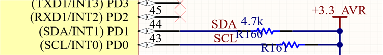
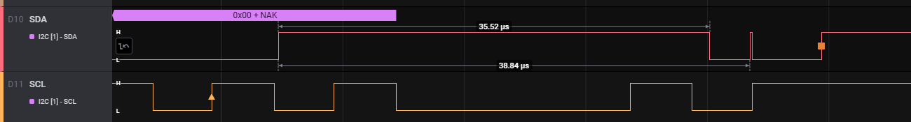
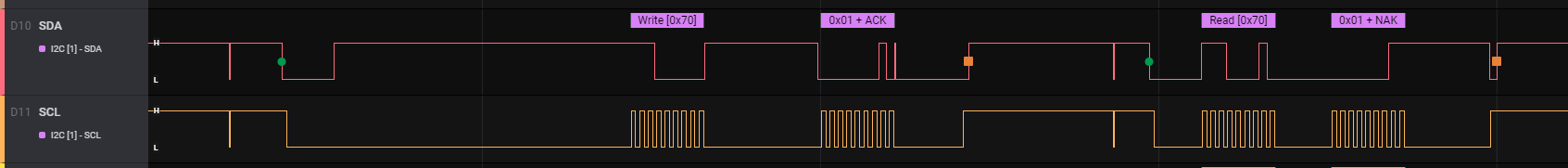
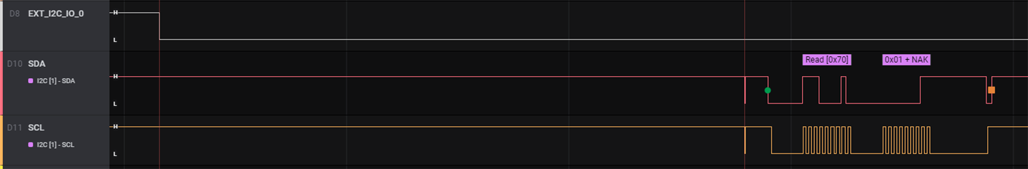
I have the mux fully operational and have been using it for weeks but am just now getting around to writing the actual interface. I want to read the status out of the mux for interrupts and for confirming buses are enabled. Even though I'm successfully enabling bus 0 via the write command, reading it back always gives 0 for bit 0. I thought perhaps reading back the register too quickly after a write was the issue so I have a second read and the value hasn't changed.

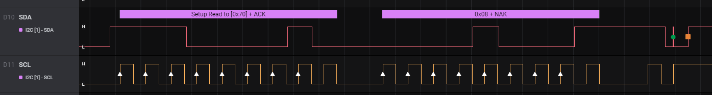
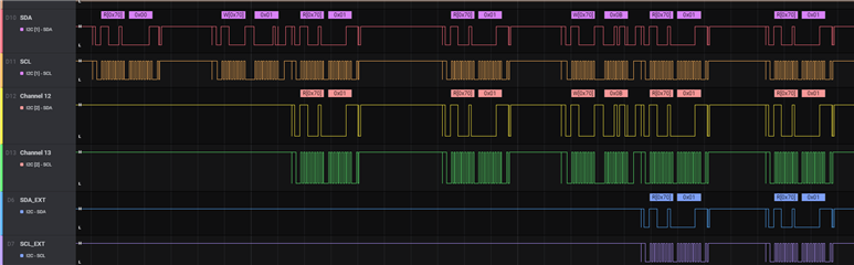
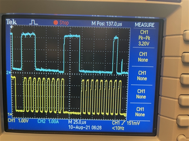
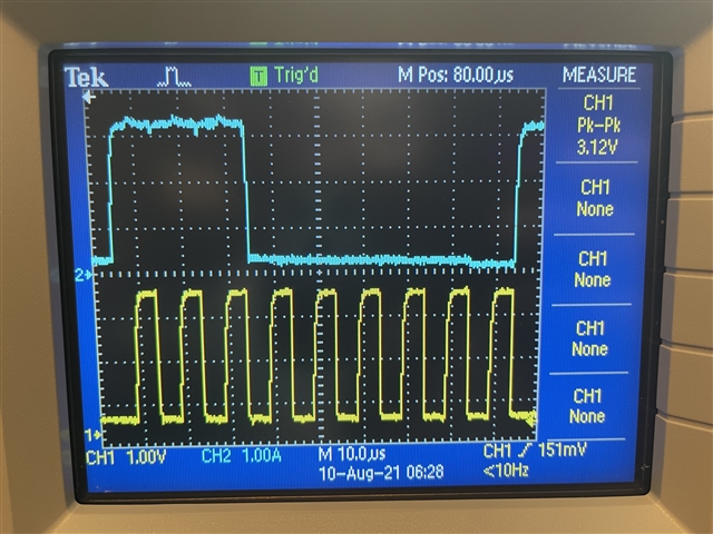
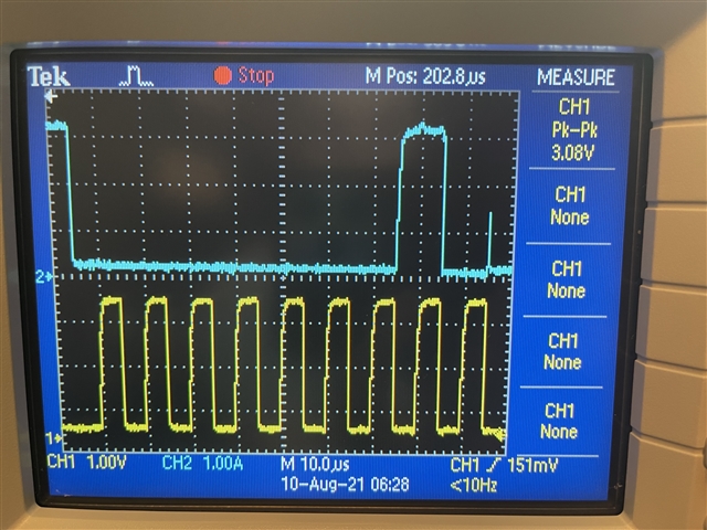
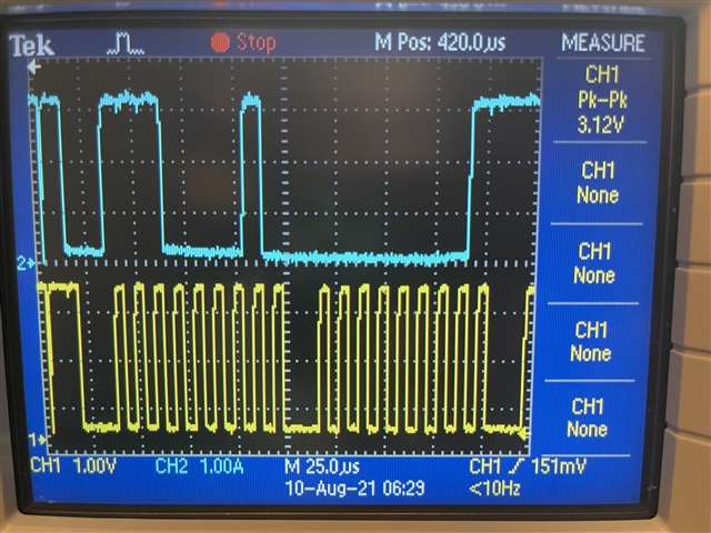
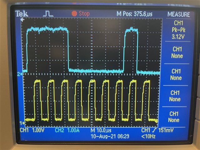
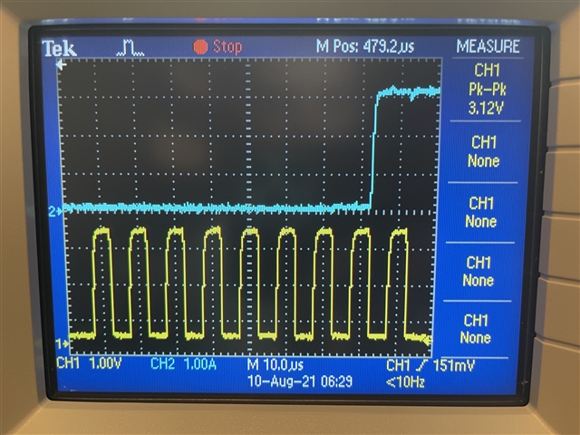
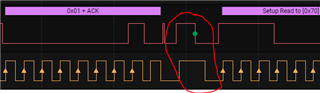
As you can see in the capture, the buses become active once the command is received. But Even sending 0x09 gives back 0x08 when reading the register.

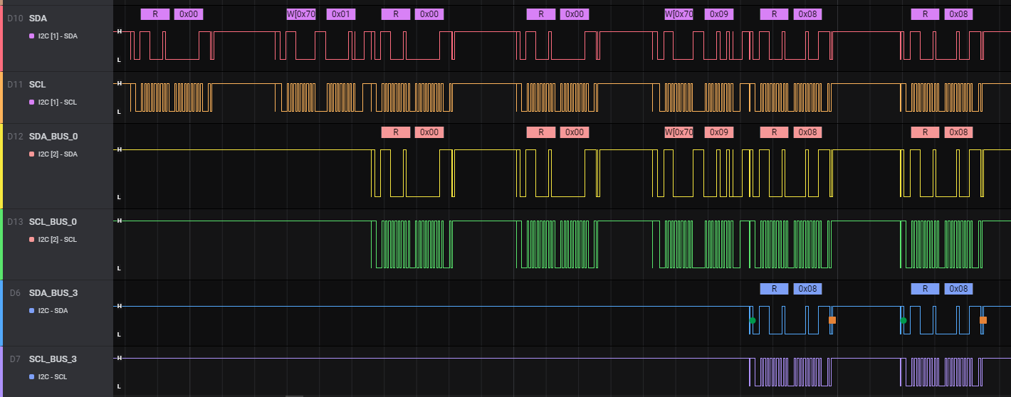
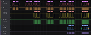
And it isn't processor side, the timing is clean. I've been using bus 0 for weeks now to read various other devices. 

  • Oddly seems to be working now. Is there a difference in a power down vs a reset? After shutting the power on the board down, it now reliably works after powering back up. Each run of my code I'm resetting the chip though so I figured if it was a buggy condition the reset would have resolved it. 

  • I guess not after all. Seems wildly inconsistent. Sometimes I get the proper status from the register, sometimes I do not. I tried including delays between write and read and it had no effect.

  • Jason,

    An engineer has been notified of this thread and will respond today. Thank you for your patience.

    Regards,

    Eric Hackett 

  • Hi Jason,

    Can you post a schematic for us to review?

    Can you also show me a write transaction to the device of 0x01h on a scopeshot (not a logic analyzer) and then one more time with a read of the device after writing 0x01h. 

    I would also like to verify, is this device a TI PCA9545A?

    EDIT: Can you also verify the address of this device is unique on your I2C bus? 

    Thanks,

    -Bobby

  • Yes the device is a PCA9545ARGYR.

    All devices have unique addresses. I have no bus collisions or anything like that. I have one board that I am developing on but potentially have a couple other boards to test this on if needed.

    When we received our boards from PCBA they had the mux populated upside down on all boards. None of these boards were powered up. We discovered it during inspection and all boards were reworked before any power was applied to the PCB.

    This is the mux, bus pull-ups are 4.7k

    Are there timing constraints I'm missing somewhere on reading/writing the status registers?

    Connection to ATMEGA2560

    Send 0x01 byte to device to enable bus 0

    Address+ack

    data byte 0x01

    read status register

    address + ack

    data byte returned is 0x00

  • Are there timing constraints I'm missing somewhere on reading/writing the status registers?

    One difference in our device versus competitors is our device does require a stop condition (not restart) in order to execute the write command. This doesn't seem like the problem since your channels are enabled. 

    Pinout matches the datasheet pinout (Good)

    Net names match (ex. SDA net matches SDA of device)

    Decoupling caps present

    Reset is biased

    Vcc is within Recommended operating Conditions

    Address pins biased to GND

    Everything I see on the schematic looks good to me. 

    One thing I do need to note though is you have a net called I2C MUX RST, is the logic of this pin ever driving high before the device powers up (I2C MUX RESET higher voltage or powered up before +3.3_I2C_MUX rail powers up?)

    I bring this up because section 8.4.1.1.1 discusses the #RESET errata. I recently worked on a return where we found that biasing RESET higher than Vcc and doing a read of the device would result in the wrong value being read from the device at different temperatures. If your biasing the RESET pin higher than Vcc, we may be seeing the same issue occuring.

    Start condition looks good here. Rise times look okay. VoLs look okay. Address sent is 0x70h write with byte 0x01h which looks correct and device ACK'd both. 
    I don't see the stop condition though. I would recommend double checking to verify it was executed properly.

    The read transaction looks like it was done properly. The stop condition however doesn't look right since SDA is high then SCL goes high. We should see the processor release SCL high while SDA is low then SDA goes high after some delay (delay time is spec'd in I2C standard)

    Can we double check what your stop conditions look like and if they are being properly done at the end of the I2C writes?

    -Bobby

  • default pin state of the mcu for i2c_mux_rst is high but they're both driven by the same +3.3 rail. It is possible one device is turning on faster, but I bet in all cases it's the mux (between the atmega and the mux).

    I will look into the stop conditions. Could be the issue, I'm unfamiliar with the spec so I'll look into that as well.

  • I don't think the scope capture shows enough of the capture to show the stop. In the image you grabbed that is the master releasing SDA and waiting for ack which happens near there on the right edge.

    Back to a logic capture, here is the stop condition where you can see SCL released fist. 

  • Hi Jason,

    It looks like the capture you show seems to have an extra clock pulse before it generates a stop condition which seems a bit funny to me. Also, this capture appears to be the read transaction since we see a NACK. It would be best to verify the stop condition on the write transaction and hopefully without that extra clock pulse. 

    Can we check the Vcc ramp rate of the device? (do this on an o-scope) I have seen issues with the PCA devices when they power up too slow or from a reference point higher than GND. 

    -Bobby

  • Thank you for pointing out the extra pulses. This is a significant bug in the library I am using. I am working on finding where it is happening but the gist is that the i2c is trying to send more clocks out and it's a race condition against the bus going idle. In the short term I have written up some bare bones code to do the i2c transfer. Stripping out the extra bits, I still do see the behavior.

    I will try to probe VCC this weekend and then I think I'll need to pull out another board to do this testing on.

  • Hey Jason,

    It looks like your bare bones code is doing a repeated start condition in between the write and read transaction. 

    Can you modify your code to perform a proper stop condition here instead of a repeated start? 

    -Bobby

  • Ok I see what I did there, I accidentally treated it like a register read. I fixed the library. it not longer sends extra clocks, see below.

    This library begins i2c transactions by resetting the i2c bus which you can see here briefly before the start. that shouldn't cause any issue should it? 

    It's working in this capture, I will try some power cycles and will get a probe on vdd if I can find a good way to get to it.

  • I think it's entirely plausible that a bad power on ramp caused the behavior. I'm using a male and female jumper wire together to enable/disable my board voltage regulator for debugging and it's a very loose fit and I think it's bouncing when I disconnect them. I can observe the regulator turning on and off as it tries to ramp up but the enable shuts it down again. 

    I can't get the register read to fail however, so it could be something to do with that and/or my i2c code. I will keep checking it but for now unless you have any other suggestions I'm thinking we may have a plausible answer.

  • I've been getting the proper bus number back from the device, and now I'm testing interrupts and I'm NOT getting those. When the INT0 line is driven low (ext_i2C_io_0), my MCU interrupts, and checks the MUX to see which bus threw the interrupt. 

    Time between interrupt and bus communication is 750 us.

    I haven't checked a second board yet.

  • Hey Jason,

    Glad to see you're now getting the proper reads after executing a write. I have seen issues with our devices when it sees a bad power up, usually though its on our PCA devices. Our newer pin to pin TCA devices have more relaxed power sequencing ramp rates.

    For the INT, are you probing one of the INT inputs of the 9545A or the output INT on pin 17? If you aren't doing the former, can you place a probe on pin 17 INT to verify it is asserting low properly?

    Also, do you have a scopeshot (using an o-scope) of the Vcc ramp rate?

    -Bobby