This thread has been locked.

If you have a related question, please click the "Ask a related question" button in the top right corner. The newly created question will be automatically linked to this question.

TUSB8020B: TUSB8020B Connection Error

Part Number: TUSB8020B

1. Connection error occurs in 5 out of 100 boards designed with TUSB8020B.
2. When connected to PC, device recognition data does not come out as upstream. At this time, the crystal does not work either.

3. I tried changing the TUSB8020B chip, but it is not recognized the same.
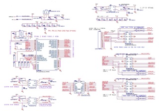
I'm attaching a schematic, so I'd like to ask for your opinion on debugging.

  • Hello Cho Young

    The hub should connect at both USB 2.0 and USB 3.0 simultaneously.  Do either connect?

    I noticed that the upstream SSTX signals do not have the series capacitors installed, this may cause some connection issues.

    Regards,

    JMMN

  • 1. The SSTX has a series capacitor connected.
    2. The content of my inquiry is that the device is not recognized by the PC when the PC and TUSB8020B are connected.
    3. For a normal board, if you connect the PC and the TUSB8020B, you can see that data is transmitted/received on the USB_DP signal line.

    4. In case of abnormal board, when PC and TUSB8020B are connected, data transmission/reception cannot be confirmed on the USB_DP signal line, and no signal is output from the crystal.

        - Check the power is normal
        - It does not work even if the parts are changed.
    That error only occurs on 5 out of 900 boards.

  • Please check the voltage levels on usb_vbus and usb_r1 on non-functional boards.

    What is the signaling on the USB DP and DM lines between the host and the hub?

    Regards,

    JMMN

  • 1. Both usb_vbus and usb_r1 signal levels are 0.5V.
    2. USB DP, DM are USB 2.0 Upstream signals.
    This is the signal line that I checked whether it works normally when connecting between the host and the hub.
    - If the connection between the host and the hub is normal, you can check the data using the instrument.
    - If the connection between the host and the hub is abnormal, the data cannot be checked using the instrument.

  • On a normal board, usb_r1 is 0v. Could this be a problem with device recognition? If yes, what is the solution?

  • USB_R1 could be low if there is no upstream USB connection or it is in suspend.

    Do you have access to a scope to check DP/DM lines?

  • 1. USB_R1 could be low if there is no upstream USB connection or it is in suspend.
    -> in the same configuration
    - Abnormal board is not recognized even if the Upstream connector is reconnected several times.
    - Normal boards are recognized normally.
    - Doesn't the crystal oscillate even in suspend mode? An abnormal board will not cause the crystal to oscillate.
    2. Do you have access to a scope to check DP/DM lines?
    -> in the same configuration
    - For abnormal boards, data is not measured when DP/DM is measured with an oscilloscope.
    - For normal boards, data is measured when DP/DM is measured.

  • Hi,

    1. The crystal will not oscillate in suspend mode.

    2. I understand there is no data on the abnormal board, but what are the voltage levels of DP and DM?  DP should be around 3.3V during suspend.

    Regards,

    JMMN

  • The DP, DM signal level on the abnormal board is 1.2V.

  • Is there a charging function on the upstream port where the hub is connected?  There are no normal USB bus conditions that would result in 1.2V signals.  Do DP and DM change, or are they constant?  Are they 1.2V constantly from power on?

    Have you confirmed that the ESD protection device on the failing boards is installed correctly?

    Regards,

    JMMN

  • 1. The hub board is only connected to the PC, nothing else is connected.
    2. When power is supplied to the hub board, the status of DP and DM is still 1.2V.
    3. Remove the ESD IC. And shall we measure the DP and DM signals?

  • Yes, please try removing the ESD device to make sure this does not impact the hub.

    Regards,

    JMMN

  • The test results are the same as in the attached table.
    In my opinion, it seems that the USB HUB IC (TUSB8020B) of the abnormal board is outputting a floating signal. What do you think?
    If you agree with me, is there something wrong with the USB HUB IC?

  • Can you check the voltage ramp for 3.3V and 1.1V, something looks incorrect here.