This thread has been locked.

If you have a related question, please click the "Ask a related question" button in the top right corner. The newly created question will be automatically linked to this question.

DS90UB962-Q1: Rin± layout

Part Number: DS90UB962-Q1

Hi Team,

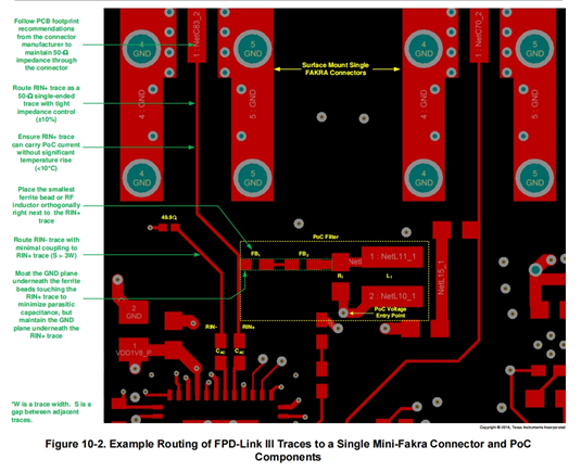
I found out that datasheet require RINX- to be placed close to the connector, and it is loosely coupled with RINX+. Customer use a single-ended signal. Why can the loose coupling pull the signal so far and close to the connector to increase the anti-interference performance? It seems that differential signals can have a strong anti-interference ability. This loosely coupled method is difficult to have this effect. On the contrary, the long-distance leading RINX- will have additional side effects, and it will be easier to draw out the radiation. It is easier to introduce additional interference. And it seems that the method you use is not of equal length.
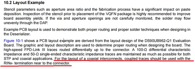
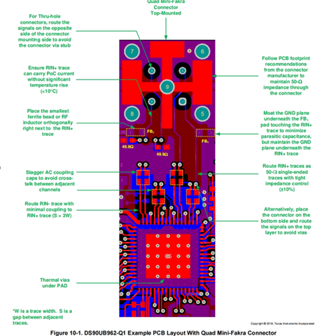
could you help to  explain, thank you!

  • Hi Amelie,

    In the COAX application, the RIN+ trace carries a single-ended signal. The RIN+ and RIN- traces do not need to be the same length, since RIN+ carries a single-ended signal. However, we do not recommend routing just the RIN+ by itself to the connector, since the signal it carries will be susceptible to EMC noise.

    We recommend routing the RIN- trace alongside the RIN+ trace, up to the connector, in order to minimize the length of trace where RIN+ is by itself. This method will reduce interference from the environment and improve EMC performance. The reason why the RIN+/- traces are loosely-coupled (S>3W) is in order to prevent the RIN+ and RIN- from introducing coupling to each other. 

    Best,

    Justin Phan