This thread has been locked.

If you have a related question, please click the "Ask a related question" button in the top right corner. The newly created question will be automatically linked to this question.

TCAN4550-Q1: Data incorrect when transimit in CANFD mode

Part Number: TCAN4550-Q1
Other Parts Discussed in Thread: TCAN4550

Hi teams

Customer is develop a new project with TCAN4450-Q1.

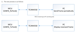
All data transimit is normal with CAN mode, with 8bit DLC.

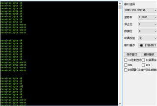
When we configure the device in CANFD mode and DLC=12bit, only MSB 8bit data is correct in receiver side, and the LSB 4 bit always be 0xAA or some other values.

Any idea how to fix this issue?

  • Hi Gabriel,

    This is an odd report. I haven't heard of only a predictable portion of a CAN frame being corrupted. 

    • Is the TCAN4550 acting as the transmitter or the receiver in this test? Or are both sides TCAN4550s?
    • Can you share the section of code where the data payload is defined and loaded into the transmit buffer/fifo and/or read from the receive buffer/fifo? I would like to make sure this is consistent with the ICs expectations. 
    • Is it possible to capture scope shots of the CAN bus during the faulty transaction? I would like to see if the frame becomes unstable from an analog point of view. 
    • How consistent is the faulty data? Are the same number of LSBs always corrupted? If not how often? Is the corrupted data consistent (i.e. always 0xAA when 0x55 is sent)? What happens when a longer payload is used? Does the corruption start in the same place in the data and continue, or is it always the last few bits?

    Let me know if you have any further questions in the meantime. 

    Regards,
    Eric Schott

  • Hi Eric

    Please check my feedback as below:

    1. Both side is TCAN4550 and one side is TCAN4550(TX) and another side is a PC(RX) already been tried. The issue phenomenon is the same.
    2. Please check the code in the attched file.TCAN4550相关代码.zip
    3. They didn't provide waveform so far.
    4. It keep happening and the percentage is vert close to 100%.
  • Hi Gabriel,

    While reviewing the code, I found the following that may be leading to a mismatch of expected and received data lengths. In CANFD_send(), the DLC variable is passed as type uint32_t. However, in the TCAN4x5x_MCAN_TX_Header struct, this field is a uint8_t. This may be causing an issue in the expected data length code. 

    The CANFD_RxTest also appears to expect a data payload of at least 16 Bytes (dataPayload[15] is referecened). However, the CANFD_TxTest is only configured to send a 12 Byte message. The CANfdRxHeader variable should be used to determine the length of the received message before the payload is accessed to ensure the proper data was received. 

    I noticed some other things in the code that may be for testing purposes, but I would still like to mention:

    • The nominal bit rate and data bit rate are the same (500kbps). Option for higher FD rate is commented out. 
    • The SID filter is configured to accept all standard ID frames (SFID2 = 0x000, all "don't cares" in filter so all IDs will match). 

    Can you please elaborate on how the data is corrupted? 

    1. Are all bytes past a certain point corrupted? Or does the number of corrupted bytes change?|
    2. What other values (other than 0xAA) appear in the corrupted part of the payload? Can you share sample payload values and mark which bytes change?
    3. What is the expected value of the ID and payload for a receiving node? Do the IDs change throughout testing or is it always the same ID? Do payload bytes (apart from the first byte which appears to be a counter) change during the test?

    Regards,
    Eric Schott

  • Hi Eric

    Thanks for your suggestion.

    1. We have modified the code in CANFD_send (), however, the result is the same.

    The hardware setup in this test have shown in below diagram:

    Detailed test process description

    1Receiving debug

    (1Signal from PC

    Figure 1

    As shown in Figure 1, the length of the transmitted signal is 64 bytes (DLC = 64), the ID is 0x179, and the values of the first 12 bytes are 0x00 ~ 0x0B.

    (2received data on mcu

    Writing test function “void CANFD_RxTest(timeout_t *timeout)”, See the file “TCAN4550_app.h/TCAN4550_app.c” for details. First, verify whether the received DLC and ID are consistent with those sent by PC, then verify whether the value of the first 12 received bytes is consistent with the value of the transmitted bytes, print the verification information of each byte through the serial port, as shown in Figure 2, in each frame of received data, the first 8 bytes are correct and the last 4 bytes are wrong.

    Figure 2

    2Sending debug

    (1) Signal from MCU

    Configure the length of the transmitted frame to 12 bytes (DLC = 12), the ID is 0x180, the first byte is the counter value, and the counter value of each frame is increased by one,and the values of the last 11 bytes are 0x01 ~ 0x0B.Every 200ms a frame is send.

    (2) received data on PC

    See the video “received data on PC.mp4”, it can be seen that the received ID and DLC are correct,the value of the first 8 bytes is also correct, the first byte shows the counter values incremented one by one. But the last four bytes are incorrect, the displayed value will jump,but the values are always the same.

  • Hi Gabriel,

    Thanks for sharing the extra info and video. It looks like the pattern of the last four bytes is repeating so I suspect it has something to do with the incrementing value. My suspicion is that this data is actually the CRC segment of the CAN frame. This may be caused if the frame itself is being limited to a data length of 8-bytes. 

    Can you confirm that the CanfdTxHeader variable is being configured (via CANFD_Config() before it is written to the buffer? If this is not done, the default header will be for a classic CAN frame which limits the data length to 8 bytes. The frame must be configured with the BRS and FDF bits enabled to allow for larger data lengths. 

    Regards,
    Eric Schott