Part Number: TPS65987D
Other Parts Discussed in Thread: TPS55288, BQ27220, LP55231, BQ51221, DRV2605L
Dear Team
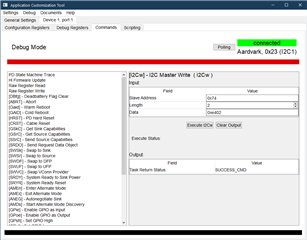
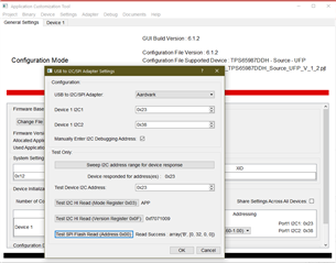
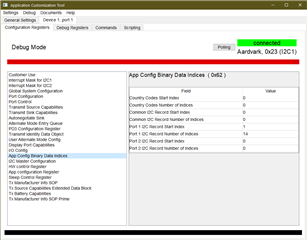
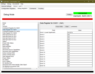
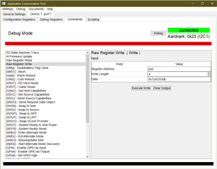
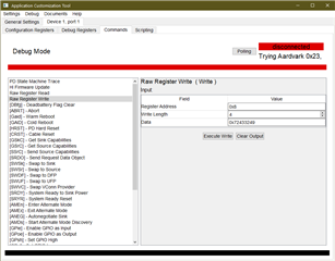
Is it possible for a host MCU, to send data/command to I2C3 over I2C1? (Something like sending data/command to SPI via I2C1)
Regards,
Majid