This thread has been locked.

If you have a related question, please click the "Ask a related question" button in the top right corner. The newly created question will be automatically linked to this question.

TPS25750: Reload patch over I2C

Part Number: TPS25750

I succesfully loaded patch over I2C. Now I want to reload another configuration. GO2P command fails with code 0x3 Task rejected.

Is it possible to reload I2C configuration again?

Datasheet states:

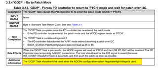
The 'GO2P' Task is considered rejected if:

• The PD controller did not enter the 'APP ' mode without receiving a patch over I2C.
• BOOT_STATUS.PatchConfigSource does not read as 3h or 4h.

6h = A configuration has been loaded from I2C.

Does this mean that I2C patch configuration CANNOT be reloaded ever again? Why?

  • Tomas,

    I will follow up with our firmware team to see why this is done, but it is likely a security issue.

    It is an unusual case that you want to change the patch.  Most of the configuration can be changed through the host interface.

    Please let me know what you specifically want to change by loading 2 different patches and I may be able to provide an alternate soliton to you

  • >but it is likely a security issue.
    But in EEPROM mode, patch can be reloaded infinite times?

    >Most of the configuration can be changed through the host interface.
    Why is there this patch upload procedure anyway then, and not just have it as default firmware? This is one of the most difficult I2C chips I have ever used. Took me 1 week to get this thing working.

    >Please let me know what you specifically want to change by loading 2 different patches and I may be able to provide an alternate soliton to you
    Everything in the GUI. I just uploaded a random test configuration to test uploading SW.

    Which items cannot be changed?

  • Tomas,

    I am sorry that this has been such an issue.

    I did review the TRM and there is a limitation that the GO2Patch only works in the NegotiateHighVoltage mode where the highest possible voltage is negotiated by default.  This is not a typical mode that most of my customers have used.

    The intended use of the chip is to establish a base configuration that supports the features that you intend to use in your project.

    The TRM that you have already read shows all of the settings that you are able to change on the fly.

    Regards,

    Chuck

  • I was able to use NegotiateHighVoltage to get into patch mode again. Now It will not accept patch uploads anymore.

    PBMc DATAX is [0x3, 0 , 0 , 0 , 0x16 , 0x32 , 0 , 0 , 0 ...]

    Do you have any example code? This chip is near-impossible to use. Error codes are completely wrong and datasheet is lacking.

    Do I need to flash lowRegion.bin or fullFlash.bin? Both?


    I'm able to start i2c patch slave and get PatchStartStatus=0 (success), but problems appear after patch transmit or PBMc call.
    I2C operations of patch transmit return success from MCU I2C interface. (I check every I2C HW call for success)

  • Tomas,

    Unfortunately, I cannot provide sample code as we cannot support all of the possible MCUs in the market place.

    You will need to use the low Region Binary for the patch because you only need one copy of the program data because of the boot method.

  • You will need to use the low Region Binary for the patch because you only need one copy of the program data because of the boot method.


    Thanks. What can be the fullBinary used for?

    Unfortunately, I cannot provide sample code as we cannot support all of the possible MCUs in the market place.

    The point is not to have compile-ready software, but a reference to look why SW is not working. I don't care if it is pseudocode, python, Go, C, javascript or made for STM32 or Microchip. I want to see a reference of working SW and compare it to mine.

  • I am looking into getting you some basic code to look at now.  I will update you as soon as I learn what is possible to share