This thread has been locked.

If you have a related question, please click the "Ask a related question" button in the top right corner. The newly created question will be automatically linked to this question.

THVD2450: Transmission compatibility issues and solutions

Part Number: THVD2450
Other Parts Discussed in Thread: SN65HVD485E

Hi

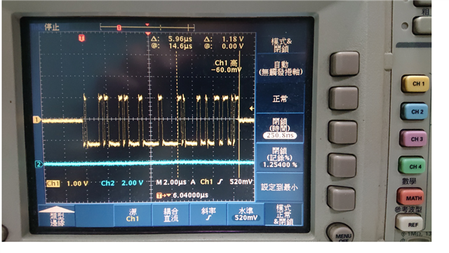
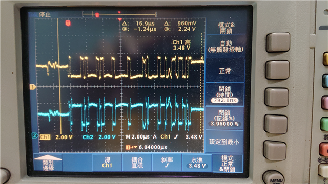
THVD2450/VSSOP8, there will be data packet loss problems in communication use

THVD2450/VSSOP8<-> THVD2450/VSSOP8 no problem ok

In order to test the compatibility of 485 ICs on the market, we use the following four types of IC

sn65hvd485e<-> THVD2450/VSSOP8 Fail

MAX13442E<-> THVD2450/VSSOP8 Fail

MAX3441EASA<-> THVD2450/VSSOP8 Fail

SN65HVD1787D<-> THVD2450/VSSOP8 Fail

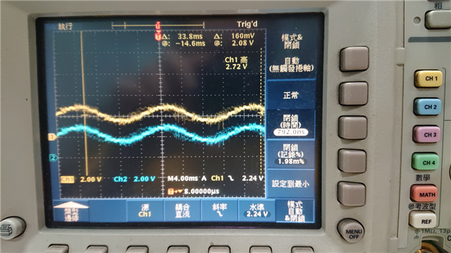
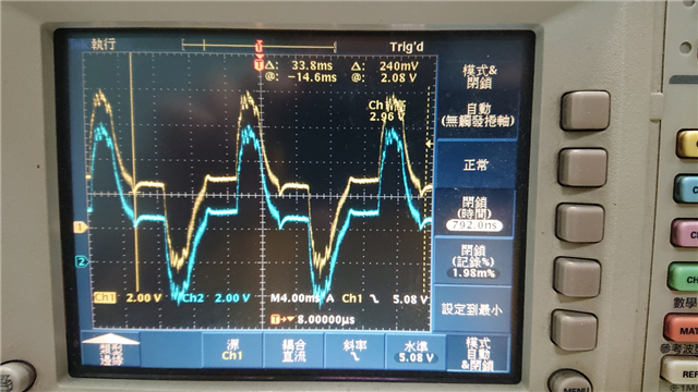
could you help check the THVD2450 schematic as below and any need adjust?

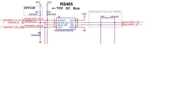
Since the MCU only has TXDEN, RE and DE are connected to TXDEN together, R3 and R25 are not uploaded, so far, the following attempts have been made:

(1) Remove the R8 resistor;

(2) Reduce the transmission Baud-rate to 115200 BPS;

None of the above methods can improve the situation. When performing MODBUS transmission, although the probability of each IC is different, the best situation is that at most 40-50 packets only missed data once, although there is no problem if both communication parties share the same ground. , But this will lose the meaning of using RS485. Is there any special attention to THVD2450 IC?

  • RS-485 requires proper termination at both ends of the bus.

    Please show an oscilloscope trace of the bus signals.

  • Gareth,

    As Clemens said, termination is needed on RS485 buses at both ends. If the termination isn't present, this could cause issues in signal integrity. Capturing oscilloscope screenshots of the bus pins will be very helpful as well so we can see what A and B waveforms look like and this may give some clues as to the root of the communication issue. .

    Can you also share the failure criteria for each fail you referenced? And the exact procedure for each test?

    Regards,

    Eric Hackett 

  • Hi Eric

    Since the transmission failure will almost always occur as long as multiple packets are continuously transmitted, the attachment file of the letter is the RS485 +/- waveform when the transmission fails in the case of continuous transmission.

  • Gareth,

    Is this the differential between A and B being plotted, or something else? And was termination added to help? I appreciate the measurement data, but we need a bit more information to understand what we're looking at.

    Regards,

    Eric Hackett 

  • Hi Eric

    The following signals are measured when the terminal resistance of the sn65hvd485e terminal and the terminal resistance of the thvd2450 terminal are both 120 ohms. The difference in the levels of the AB differential signals on both sides seems to be a bit large. Both sn65hvd485e and thvd2450 are powered by 5V, but even if sn65hvd485e is powered by 5V, the differential signal of AB is still only +/-2V. The current solution is to pull high with 10K ohms on A BUS and pull low with 10K ohms on B BUS. Neither party will have a high probability (50%). There is a problem with the signal, but there is a risk that the pull-up power supply is full of high voltage, because the 485 transmission does not need to share the ground wire. In addition to sn65hvd485e, I also tried thvd2450 and SN65HVD1787D, MAX3441EASA, MAX13442E for RS485 communication. If only terminal resistors are used, the probability of communication failure is as high as 50%. Is there any compatible IC or other solutions for thvd2450?

  • Hi Gareth,

    Can you show the A signal on channel 1 and B signal on channel 2? I would like to see the relationship of each signal with respect to the ground of the driving IC. 

    How long is the cable that connects the two nodes being tested? Are there more than two nodes connected in the test? Or is this only point-to-point communication? 

    Are there any combination of RS-485 transceivers that work with the current setup? Or does the test always drop packets with any transceiver?

    Regards,
    Eric Schott

  • Hi Eric

    The following is the transmission waveform of sn65hvd485e (connect the GND of sn65hvd485e to the GND of the probe):

    The following is a transmission waveform thvd2450 (GND thvd2450 access probe to the GND):

    The cable length of RS485 is 60cm; There is only one sn65hvd485e and one thvd2450 on the RS485 Bus; The test process is that sn65hvd485e is used as the client side of Modbus and thvd2450 is used as the server side of Modbus. The transmission failure has the following two situations:

    1. thvd2450 did not receive the data packet sent by sn65hvd485e, because the R pin of thvd2450 did not output or the data was wrong;

    2. After receiving the packet, thvd2450 sends back sn65hvd485e, sn65hvd485e did not receive the returned packet, because the R pin of thvd2450 is not output or the data is wrong;

    The above two situations are probabilistic. When Picture01.JPG in the attached file of the letter is not transmitted, connect the probe GND to the GND of sn65hvd485e, and the measured waveforms of A and B pins; When Picture02.JPG is not transmitted, the probe GND is connected to the GND of thvd2450, and the measured waveforms of A and B pins.

  • Gareth,

    It's clear that signal integrity is the issue here; the transmission waveform from the THVD2450 looks like their may be some kind of grounding issue on that transceiver. Can you explain what the last two images are in your last post? One looks like 60Hz is coming through on the oscilloscope when the bus should be idle, and the next looks like A and B are directly following each other. 

    Can you share a block diagram of both nodes in the system, how they are powered, and how they are grounded?

    Regards,

    Eric Hackett