A related question is a question created from another question. When the related question is created, it will be automatically linked to the original question.
If you have a related question, please click the "Ask a related question" button in the top right corner. The newly created question will be automatically linked to this question.
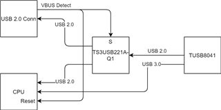
TUSB8041: Help review schematic diagram of TUSB8041.
Leave unused SS ports unconnected, do not pull to ground.
If SMBUSz is pulled low, the hub will be in SMBUS mode and will not exit until a SMBUS host configures the hub.
USB_VBUS is a detection input that should only be high when a host is connected. Please choose the resistors so it is around 500 mV when high.
If the PWRCTL outputs are not used, they should be left unconnected.
I see the switch allows for the upstream USB 2.0 port to be routed to an external connector. Please note that USB_VBUS should toggle if the switch is set during normal operation. Also, having the USB 2.0 routed to an external port while the USB 3.0 remains connected elsewhere is not a compliant condition and may cause interoperability issues.
If we just want to read the register status when necessary, and hope that the Hub can be started in its own default state during normal startup, how should we configure it?
We currently design this way(as shown in the figure below). After the external USB interface is plugged in, it will divide the external VBUS signal to 3.3V, and then this signal will pass through some logic circuits to put the CPU in the reset state, so that the Hub’s Upstream port which connected to the USB 3.0 Host is theoretically in a reset state. Can this eliminate the "the USB 3.0 remains connected" state?
In addition, the VBUS signal will also maintain the enabled state of the power supply such as 3.3V/5V on the board, and the TUSB8041 is also powered by the power supply on the board. Does this also require USB_VBUS to have a toggle action?
Holding the CPU in reset should address the possible USB 3.0 interoperability condition.
The board power is enabled by VBUS? How is it powered when there is no external USB interface condition? Will it toggle when the external interface is connected?
Yes, when the USB cable is plugged into the connector, the on-board power supply will be enabled through the connector’s VBUS to supply power to the Hub. This signal will also set the on-board CPU and PMIC in the reset state; when the USB cable is unplugged, VBUS=0, the PMIC and CPU on the board are released from the reset state. At this time, the on-board power supplies power to the CPU and Hub which is controlled by PMIC, and the USB switch connects D+/D- to the CPU for communication.
when the USB cable is plugged into the connector, because the power supply is controlled by the line-or method, there will be no re-power on. When the USB cable is unplugged, the power will be turned off until the PMIC is released from the reset.
by the way,when USB cable plug in,the power will not power off and power on again,when USB cable unplugged ,the power supply will power off and power on again
Yes, this design ensures that when the USB cable is inserted, the power supply to the USB Hub will not be interrupted, the CPU and PMIC remain reset, and the USB channel is connected to the USB cable through a signal switch(TS3USB221A-Q1)