This thread has been locked.

If you have a related question, please click the "Ask a related question" button in the top right corner. The newly created question will be automatically linked to this question.

DS90UB962-Q1: Can't output normal video using no.4 camera

Part Number: DS90UB962-Q1

Hi Team,

As tile, we can get normal video when we connect no.4 camera. And the other 3 cameras can output the normal video via 962 

I check the camera that we are using are 4 X Camera AR0147 : 4 X 1344X968 30p 16bit/12bit.

 For each camera data rate need is around 1Gbps. And 962 is Quad 3-Gbps Deserializer Hub Aggregates Data From up to 4 Sensors Simultaneously. So our data rate is related low and 962 can fully supported.


I discussed with customer and I summarize the conclusion as below. 

  1. REFCLK = 26MHz- CSI-2 Synchronous Mode
  2. UB962-Q1 can correctly output the video if you only connect 3 camera module. (port0/port1/port2)
  3. UB962-Q1 can correctly output the video when you connect 2 camera module. (port0/port1 or port2/port3)
  4. Camera module is using 953 as serializer.

So we don't think the root cause is from the SI problem in port3. May you help let me know if there is any method can verify the root cause?

Regards,

Roy

  • Hello Roy,

    This sounds like a BW aggregation problem - basically what is described here in this training module:

    https://training.ti.com/csi-2-aggregation-breakdown?context=1134310-1139225-1148220 

    Can you please provide the following details?

    - What CSI-2 output lane rate is being used on the 962?

    - How many CSI-2 lanes on the 962?

    - For the video cameras, what is the vertical total number of lines for this sensor configuration?

    - What is meant by 16bit/12bit? 

    Best Regards,

    Casey 

  • Hi Casey,

    Thanks for information. I will see the training video tomorrwow/

    Please see my response first.

    - What CSI-2 output lane rate is being used on the 962?

    We set CSI_PLL_CTL as 1.664Gbps, REFCLK= 26

    - How many CSI-2 lanes on the 962?

    4lanes

    - For the video cameras, what is the vertical total number of lines for this sensor configuration?

    I will check this with customer.

    - What is meant by 16bit/12bit? 

    Sorry for typo. This is RAW16 and RAW12

    Roy

  • Roy,

    Ok, can you please double confirm also that the CSI-2 output is set to 1.6G mode and not 800Mbps mode? 

    Best Regards,

    Casey 

  • Hi Casey,

    All I need to check is only CSI_PLL_CTL Register : 0x1F[1:0] should set 00?

    Do I miss anything?

    Roy

  • Hello Roy,

    That should be all that is needed - ok well please do send feedback on the sensor Vtotal here and also can you provide reg dumps for all 4 RX ports when you are in this issue state?

    Select each port one by one with 0x4C and dump the regs that way we can see all the port specific statuses 

    Best Regards,
    Casey 

  • Hi Casey,

    Please see below.

    1. Total V = 1396
    2. We checked  CSI_PLL_CTL Register : 0x1F[1:0] = ‘00’
    3. The register dump is as attached.962 reg dump.txt
    4. In addition, is the register set 4port BW together? 

    Many thanks.

    Regards,

    Roy

  • Hi Casey,

    Correct the timing info.

    Htotal, Hactive

    1672, 1344


    Vtotal, Vactive,

    1076, 968

    Roy

  • Hello Roy,

    When looking through the reg dumps it appears that you are trying to do a sycnhronized forwarding here of the attached cameras and register 0x22 indicates a synchronization failure. So I think the issue here is that all 4 cameras are not synchronized within 1 video line per the datasheet requirement:

    How exactly are the cameras being synchronized here? Have you verified that they are indeed synchronized to within 1 video line? One method you could try to do this would be to map the Frame Valid and Line Valid signals from each RX port to GPIOs and then you can monitor them on the scope or logic analyzer to see what is happening from camera to camera. 

    Also I would suggest to make sure that your init script follows this order:

    - Enable all cameras streaming and synchronized 

    - Enable CSI-2 in 0x33 

    - Forward all 4 cameras at once by selecting 0x20 = 0x00

    Best Regards,

    Casey 

  • Hi Casey,

    1. How exactly are the cameras being synchronized here?

    The AR0147 have a trigger design, when the trigger pin pull high, camera send the mipi data to the UB953.

    And the trigger connect to UB953 gpio1, the ub953 gpio1 will follow the status of ub962 gpio0.

    CV22 trigger -> UB962 GPIO0 -> UB953 GPIO1 -> AR0147 Trigger


    2. Have you verified that they are indeed synchronized to within 1 video line?

    Unfortunately, customer doesn’t have equipment to measure MIPI signal.

    But maybe they can check the synchronization of the each port gpio trigger first.


    3.I also checked the 3 input register dump, the register 0x22 =0x5, it also showed “Synchronization failure” .

    But the video output is fine.

    962_3input reg dump.txt

    Regards,

    Roy


  • Hello Roy,

    It seems like the cameras may not actually be fully synchronized here which could be leading to this problem. So what I would suggest is to probe the part to see how close the sync actually is. You can do this with simple logic analyzer equipment - you do not need MIPI analysis tools. The 962 has a feature to map the received Frame Valid and Line Valid signals from each camera to GPIO outputs which corresponds to the VSYNC and HSYNC signals respectively. Using a logic analyzer we can capture those signals and compare the alignment to see if they are indeed synchronized to within 1 line. 

    Please see the datasheet registers 0x10-0x17 for GPIO controls to map out those signals. Can you please probe them with a logic analyzer to compare from RX port to RX port?

    Also note that the FWD_SYNC_FAIL is a latching register which clears on read so I would suggest to read it back multiple times to clear any initial error flag and then you can use it to monitor the sync status afterwards. 

    Best Regards,

    Casey 

  • Hi Casey,

    1.Camera Trigger signal

    We measured the trigger signal from each 953 GPIO1.(Trigger_sync.jpg)

    The trigger signal is a V-Sync signal.

    CV22 Master_VSYNC -> UB962 GPIO0 -> UB953 GPIO1 -> AR0147 Trigger

    The synchronizations looks fine.


    2.Frame valid and Line Valid

    Because we don’t have all HW point for 962 gpio, so we can only use 2 gpio to test it

    But we want to know about the solution if “Line Valid” is the root cause .

    Roy

  • Hello Roy,

    So the signal above is the GPIO output from 953 to the sensor? What we need to check instead is GPIO from the 962 which is corresponding to the received LV/HV signals from the RX ports instead. So if you only have access to 2 GPIO, then you must compare the cameras to each other with only 2 ports at a time; ex. RX0 to RX1, RX1 to RX2, etc. 

    Best Regards,

    Casey 

  • Hi Casey,

    Thanks for information. 

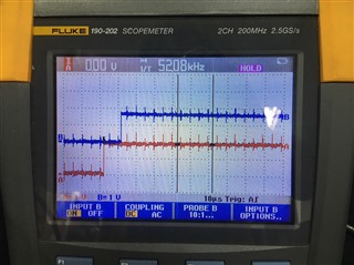
    We got the line valid and frame valid signal as below.

    It seems signals are not sync, how can we solve it?

    Regards,

    Roy