This thread has been locked.

If you have a related question, please click the "Ask a related question" button in the top right corner. The newly created question will be automatically linked to this question.

DS90UB941AS-Q1: FPD-Link differential trace impendence layout review

Part Number: DS90UB941AS-Q1

Hello Team,

My customer is using the DS90UB941AS-Q1,  the test result show low impendence the ESD component location. and the result as below:

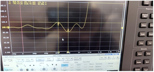
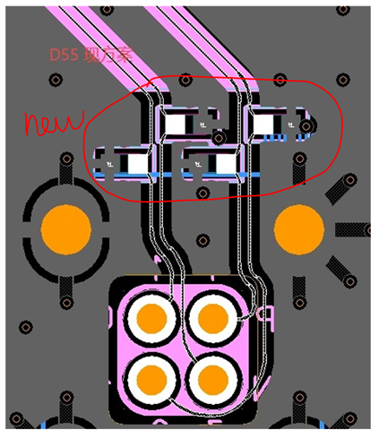
customer has done some modify between original layout and new layout.

original

new

  • Hi Xiaowei,

    The impedance snapshot is very bad. The mismatch hit at many spot not just the ESD diode protection.

    1. Did you have the anti-pad for all the discrete components where it lands on the high speed path?
    2. Did you calibrate your impedance analyzer before you start the measurement?
    3. What is the rise time that you set on your impedance analyzer?
    4. Was the measurement done when power on or off?
    5. Did you take the measurement from the connector to the device?
    6. You might want to put your finger on the trace or component to determine location of the impedance mismatch.

    Aaron

  • Hello Aaron,

    customer confirmed the mismatch hit at ESD diode protection, and the front point is test solder position, so don't care it. and I would like to clarify that the measurement is base original design , customer want to use the new design to optimize it, do you think the issue can be improve? 

    Did you have the anti-pad for all the discrete components where it lands on the high speed path?

    feedback: yes, the area is 1.25 times that of the pad.

    Did you calibrate your impedance analyzer before you start the measurement?

    Feedback: Yes.

    What is the rise time that you set on your impedance analyzer?

    Feedback: 100ps

    Was the measurement done when power on or off?

    feedback:  during power off.

    Did you take the measurement from the connector to the device?

    Feedback: the measurement has done between AC capacitor and connector.

    You might want to put your finger on the trace or component to determine location of the impedance mismatch.

    feedback: customer confirmed the mismatch location at ESD point.

  • Hi Xiaowei,

    Since you mentioned that the measurement was done in between the AC caps and connector, I assumed that you have the AC caps removed. What is the data rate that you are running for the 941AS? Do you have the sim result for the new design?

    Aaron