This thread has been locked.

If you have a related question, please click the "Ask a related question" button in the top right corner. The newly created question will be automatically linked to this question.

TPS65987D: CC Pin and datasheet Question

Expert 1065 points
Part Number: TPS65987D

Hi TI team,

I have two questions about TPS65987D,
1.)I'd like to know, does this mean only 600mA current can through the CC pin?

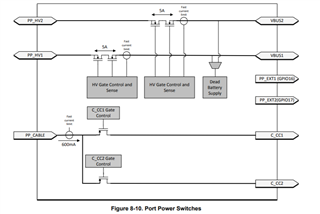
2.) Does this circuit used to detect the dead battery?

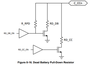
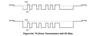
3.) What does this figure mean, I read the datasheet but I don't understand.

  • Jack,

    The CC lines in a type C system have several functions.

    1.  It is a data communications link to send PD messages (Question 3)

    2.  It can provide a power supply to certain cables (600mA current limit 5V supply from question 1)

    3.  It is used to determine the nature of the 2 ports connected together on the cable.  Your question 2 has some of this functionality described on it.  

    The USB type C/PD specification is a good source of information on all of the features that are described in the datasheet to get further understanding of what is happening on the pins.

  • Hi Chuck,

    According to your answer, I still have some questions,
    1.) Why the DC bias is different, one is higher the other is lower. (Question 3)


  • Jack,

    There are 3 possible values of RP (Pull Up Resistor) and 3 possible values of Rd (Pull Down resistor)  

    The type C connector uses the combination of these possible outcomes to determine the current limit for a legacy PD connection.  It can be 900mA, 1.5A, or 3A depending on the current/voltage reference.  This is described in the USBIF type C specification.

    The TPS65987D is able to present all versions of RD for detection as well as all 3 possible values for RP to advertisement. 

    This figure shows the dead battery case as well as a representation of the other possible resistors.

    Regards,

    Chuck