This thread has been locked.

If you have a related question, please click the "Ask a related question" button in the top right corner. The newly created question will be automatically linked to this question.

TLK10034: access problem on the MDIO interface

Part Number: TLK10034

Hello support team,

We are having problems communicating with TLK10034.

The component does not respond when we are trying to access the MDIO bus. Do you have any suggestions on what might cause this problem?

On our board the TLK10034 is powered with 1.8V and 1.0V. The 1.8V power supply is supplied first, then the 1.0V power supply .

The 156.25MHz clock is generated on the differential input REFCLK0. Then the Reset is released.

The pins MODE_SEL and ST are set to 0.

The MDC clock is continuous. It was originally at 1.8MHz, we lowered it to 1.0MHz.

The transceivers are not in Power down mode (PDTRX _N is set to 1).

There is no other PHY on MDIO interface

 We are trying to access the registry PMA_DEV_IDENTIFIER_1:

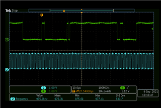
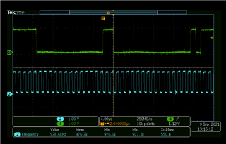
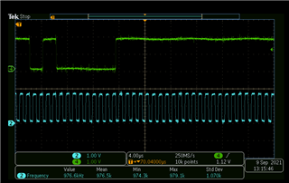
 On the oscillograms below the MDC clock is on channel 2, the MDIO signal on channel 1.

On attached Pictures:

-The 2 accesses in clause 45: writing the address and reading the register

- Zoom on writing the address

-Zoom on reading the register: the component does not respond:


Best regards,


Robin

  • Hi, see debug inputs below.

    • How are PRTAD[4:0] configured? 
      • PRTAD[4:2] selects the MDIO port address. Selecting a unique PRTAD[4:2] perTLK10034 device allows 8 TLK10034 devices per MDIO bus. Each channel can be accessed by setting the appropriate port address field within the serial interface protocol transaction.
      • The TLK10034 will respond if the 3 MSB’s of the port address field on MDIO protocol (PA[4:2]) matches PRTAD[4:2].
    • Are you following the RESET_N sequence upon power up per datasheet?
    • Is TESTEN grounded?
    • Are GPI[2:0] pins grounded?
    • There are multiple power supply pins (VDDD, VDDA, DVDD, VPP, VDDT, VDDRA - VDDRD, VDDO.) Please ensure their configuration is per TI datasheet

    Thanks,

    Rodrigo Natal

  • Hi,

    PRTAD[4:2] pins are grounded through  4,7KOhm resistors. TLK10034 is the only connected device on MDIO interface.

    We have probed the 32 addresses.

    The only sequence constraints I found in the datasheet is 10us minimum duration after power stabilization. Reset is deasserted by management processor after 500ms.

    TESTEN pin is grounded through 4,7KOhm resistors.

    GPI[2:0] pins are grounded through  4,7KOhm resistors.

    The  power supply pins configuration seems to me correct.

    Thanks,

    Robin

  • Hi,

    I'm honestly not sure why you are having issue with MDIO communication to TLK10034. This is an old product that has been in production for a long time, and being used in multiple customer applications relying on MDIO. Two suggestions below:

    1. Do one last sanity check of your system schematic TLK portion by comparing with the schematic used for the TI evaluation board
    2. Try ordering a TI TLK10034 evaluation board and doing some bring up using the TI GUI software

    Thanks,

    Rodrigo Natal

  • Hi,

    I have perform sanity check, and I didn't find anything.

    I have try to cummunicate with TLK10034 using a Marvell MDIO probe, PHY is not responding.

    I have no doubt that on evaluation board we would be able to communicate with TLK10034.

    I get the feeling that TLK10034 is stucked during initialisation.

    Is there a way to verify that the component is initialized?

    what could block initialization?

    IC_TLK10034.pdf

    Thanks,

    Robin

  • Hi Robin,

    I frankly can't figure out what could be the issue here preventing you from having MDIO communication. The only hypothetical issues I can think of are below.

    • Ensure proper RESET_N initialization: This pin must be held asserted (low logic level) for at least 1.5V/1.8V VDDO0 10us after device power stabilization.
    • Ensure PRTAD pins are correctly configured relative to system MDIO address commands
    • On the datasheet, there's the following statements as it pertains to MDIO pins
      • MDC: Note that an external pullup is generally not required on MDC except if driven by an drain/open-collector clock source.
      • MDIO: This signal must be externally pulled up to VDDO using a 2kΩ resistor.
    • Not sure how this affects MDIO communication but the PDTRX pins should be pulled up to VDDO 

    Thanks,

    Rodrigo Natal

  • Hi Rodrigo,

    I have checked the potential issue.
    For MDIO, I use an opain-drain level shifter (LSF0102DCU) (The TLK10034 having a MDIO bus referenced to 1.8V,  the ethernet switches bus referenced to 3.3V).On the TLK10034 side I have pull-ups of 2kOhm on the MDC and MDIO signals.
    On the Matrix side, I have a Thevenin termination on the MDC signal and a pull-up on the MDIO signal.

    Is the MDIO part independent of the REFCLK clocks?

    Thanks,

    Robin

  • Related to: "Is the MDIO part independent of the REFCLK clocks?"

    • That is correct.

    Thanks,

    Rodrigo Natal