This thread has been locked.

If you have a related question, please click the "Ask a related question" button in the top right corner. The newly created question will be automatically linked to this question.

DS90UB954-Q1EVM: Framerate measurement

Genius 9880 points
Part Number: DS90UB954-Q1EVM
Other Parts Discussed in Thread: ALP

Hi,

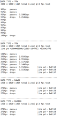
Customer is using ALP to follow the User guide for DS50UB954 and DS50UB953. According to them, they could run the test script and got the desired result on the information tab, which was 3840 bytes by 1080 lines.

However, they want to measure the framerate of the data sent.

They want to know if there are a script to measure or set the following:

1. measure or set the framerate of transmission?

2. measure the maximum bandwidth? Datasheet says 4.6Gbit/s, but we want to actually measure it.

3. when they send data through MIPI to FPD-Link, how many % overhead it adds? Is there a way to measure this as well?

Thank you in advance.

Regards,
Maynard

  • Hello Maynard,

    1) You can measure the frame rate using a scope. To do that you shall configure the FrameValid feataure to be output on GPIO0 using the below code, and measure it.

    Reg0x10 = 0xC1

    2) You can't measure that but you can calculate it as per 953 datasheet, Table 7-6. Clocking Modes.

    3) MIPI overhead is added by the image sensor, which we can't influence. But if you are asking about FPD-LINK overhead, this can be calculated as per the Clocking Modes Table mentioned on #3.

  • Hi Hamzeh,

    Customer have follow up questions/confirmations, see details below.

    "

    1) You can measure the frame rate using a scope. To do that you shall configure the FrameValid feataure to be output on GPIO0 using the below code, and measure it.
    à I did it and ran the preDef script (953to954_patgen_*.py) to verify it sends in 30Hz with o-scope. I could raise it up to 92Hz by modifying the line period on the script, but from 93Hz the vertical line drops from 1080 to 540. I wonder if that reached the maximum bandwidth and 953 cuts the vertical lines by half.

    It is running at 100MHz, and using the table 7-6, I could find that CSI Bandwidth is 3.2Gbps. Assuming it is 8-bit color data, my calculation comes to: 3840 x (1080 + 45 (back, front porch)) * 92fps * 8bit = 3.180Gbps, which is below 3.2Gbps. Using the same calculation, at 93fps, it becomes 3.214Gbps which is above 3.2Gbps.

     Since the forward channel data rate is 4Gbps, is the FPD Link overhead 25% of the CSI data transmitted? Not sure if I calculated it right..

    Additionally, could you explain what the CSI Data Identifier means in the preDef script? Originally, it is 0x1E which I assumed to be 8-bit data as mentioned above. The script gives 0x24 = RGB888, 0x2C = RAW12, 0x2B = RAW10. Could you explain what these RAW12 and RAW10 mean?

    Because when I tried sending 1360 x 1020 at 272fps (3.152Gbps), it drops the vertical line to 510. However, when I switched to RAW12, it did not drop and sends 1360 x 1020 at 272fps.

    Additionally, this could be ignored, but I found something odd.
    As mentioned, 1360 x 1020 @272fps drops the vertical line by half. However, at same 272fps, when I used line period = 0x0159, it does not drop any vertical lines. Line period = 0x0158 drops. This is very minimal difference, yet makes a different result. It is not even close to 3.2Gbps, yet one fails and one passes. Could you explain what is going on here?

    Regards,
    Maynard

  • Yes your calculation is correct. If the CSI-2 datarate is 3.2Gbps then FPD-Link datarate is 4Gbps.

    Data identifier is data type such as RAW10, RAW12, YUV, RGB .. etc

    By increasing the line period on the sensor, you are increasing the datarate, which can exceed the specs of our SER.

  • Hi Hamzeh,

    I just received response from customer and want to confirm something regarding 953 and 954. Below is the details.

    "I tested 953 and 954 with different data type and got the result below, which is odd.


    From my knowledge, YUV and RGB888 carry more bit than RAW12 which is 12-bit. Thus, I expected RAW12 to transfer at higher fps than YUV and RGB. However, the transmission cuts the vertical line into half at 272fps regardless of data type. Does this result make sense to you guys? If so, could you explain how?"

     Thank you in advance.

    Regards,
    Maynard

  • Hello Maynard,

    the UB953 can support max CSI-2 throughput data = 3.28Gbps depending on the Clocking mode and REFCLK. So, you need to double check the REFCLK and Clocking mode of the 953 and then calculate the max supported datarate.

    Also I am not sure what the image sensor setting  Line pd 0x0159, 0x0158 ...etc does change!!

  • Hi Hamzeh,

    Just received response from customer, details below.

    "

    Why would RGB and RAW have the same bandwidth? 

    RGB888=24bits(rgb)=Takes 1pix/3Bytes to transfer

    RAW12=12bits(grey)=Takes 1pix/1.5Bytes or 2pix/3Bytes to transfer

    What I'm assuming is happening is the RAW12 also takes 1pix/3Bytes similar to RGB. So can we configure RAW12 to a packed or double data format? What is the size of the bits/pix?

    "

    Regards,
    Maynard

  • Hello Maynard,

    RGB888 requires a 3-byte block size which is equal to the pixel size.
    RAW12 requires a 3-byte block size which is equal to 2 pixels.

    RGB888 has 24bits/pixel

    RAW has 12bits/pixel

  • Hi Hamzeh,

    Customer have followup question, see detail below.

    So why would RGQ888 and RAW12 have the same maximum bandwidth? My experiment showed they have the same bandwidth, but shouldn’t RAW12 be able to send more data?

    Regards,
    Maynard

  • Hello Maynard,

    I am not sure why you see the same datarate! Normally RGB888 requires double the bandwidth of RAW12.