This thread has been locked.

If you have a related question, please click the "Ask a related question" button in the top right corner. The newly created question will be automatically linked to this question.

DS90UB941AS-Q1: PCLK_DETECT error

Part Number: DS90UB941AS-Q1

Hi Team,

My customer now use 941 (DSI 1920*2*720) and 2*948(1920*720). And found error in 0Ch register D2, PCLK_DETECT  will become 0 and then display is abnormal.

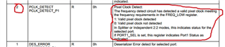
Customer already try to change 0x5D and 0x5E register but still PCLK_DETECT have error.

Could you kindly help to give some advice?

Here are the initialization

{0x0c, 0x01, 0x03, 0},//reset all

{0x0c, 0x01, 0x08, 0},//Disable DSI
{0x0c, 0x1E, 0x01, 0},//Select FPD-Link III Port 0
{0x0c, 0x03, 0x9A, 0},//Enable I2C_PASSTHROUGH, FPD-Link III Port 0
{0x0c, 0x17, 0x9E, 0},
{0x0c, 0x0E, 0x03, 0},
{0x0c, 0x0F, 0x03, 0},
{0x0c, 0x4F, 0x0C, 0},//Set DSI_CONTINUOUS_CLOCK, 4 lanes, DSI Port 0
{0x0c, 0x5B, 0x07, 0},//Force Splitter mode
{0x0c, 0x56, 0x80, 0},//Enable Left/Right 3D processing to allow superframe splitting
{0x0c, 0x32, 0x80, 0},//IMG_LINE_SIZE0 7:0
{0x0c, 0x33, 0x07, 0},//IMG_LINE_SIZE1 12:8
{0x0c, 0x5D, 0x00, 0},

{0x0c, 0x1E, 0x02, 0},//Select FPD-Link III Port 1
{0x0c, 0x03, 0x9A, 0},
{0x0c, 0x17, 0x9E, 0},
{0x0c, 0x4F, 0x0C, 0},//Set DSI_CONTINUOUS_CLOCK, 4 lanes, DSI Port 1
{0x0c, 0x5B, 0x07, 0},//Force Splitter mode
{0x0c, 0x56, 0x80, 0},//Enable Left/Right 3D processing to allow superframe splitting
{0x0c, 0x32, 0x80, 0},//IMG_LINE_SIZE0 7:0
{0x0c, 0x33, 0x07, 0},//IMG_LINE_SIZE1 12:8
{0x0c, 0x5D, 0x00, 0},

{0x0c, 0x1E, 0x01, 0},
{0x0c, 0x36, 0x00, 0},
{0x0c, 0x37, 0x80, 0},
{0x0c, 0x38, 0x7F, 0},//x end 7:0
{0x0c, 0x39, 0x07, 0},//x end 12:8
{0x0c, 0x3A, 0x00, 0},
{0x0c, 0x3B, 0x00, 0},
{0x0c, 0x3C, 0xCF, 0},//y end 7:0
{0x0c, 0x3D, 0x02, 0},//y end 12:8
{0x0c, 0x40, 0x04, 0},
{0x0c, 0x41, 0x05, 0},
{0x0c, 0x42, 0x0C, 0},

{0x0c, 0x1E, 0x02, 0},
{0x0c, 0x36, 0x00, 0},
{0x0c, 0x37, 0x80, 0},
{0x0c, 0x38, 0x7F, 0},//x end 7:0
{0x0c, 0x39, 0x07, 0},//x end 12:8
{0x0c, 0x3A, 0x00, 0},
{0x0c, 0x3B, 0x00, 0},
{0x0c, 0x3C, 0xCF, 0},//y end 7:0
{0x0c, 0x3D, 0x02, 0},//y end 12:8
{0x0c, 0x40, 0x08, 0},
{0x0c, 0x41, 0x05, 0},
{0x0c, 0x42, 0x0C, 0},

{0x0c, 0x30, 0x01, 0},
{0x0c, 0x01, 0x00, 100},

  • Hi Amelie, 

    Is this issue happening on both ports, or is only one of the two displays have this issue?

    Can you provide a full register dump of both ports on 941?

    Regards, 

    Logan

  • Hi sir,

    This issue only happened on port1, port0 is normal. We try to change this ds90ub941 chip to another main board,  this issue follow ds941 chip.

    console:/ # i2cdump -f -y 0 0x0c                                               
    No size specified (using byte-data access)
         0  1  2  3  4  5  6  7  8  9  a  b  c  d  e  f    0123456789abcdef
    00: 1a 00 00 9a 00 00 58 00 00 01 00 00 61 30 00 00    ?..?..X..?..a0..
    10: 00 00 00 8f 00 00 fe 9e 7f 7f 01 00 00 00 02 00    ...?..?????...?.
    20: 0b 00 25 00 00 00 00 00 01 20 20 a0 00 00 a5 5a    ?.%.....?  ?..?Z
    30: 01 09 80 07 0c 00 00 80 7f 07 00 00 cf 02 81 02    ?????..???..????
    40: 08 05 0c 00 00 00 00 00 00 00 00 00 00 00 00 0c    ???............?
    50: 16 00 00 00 02 10 80 02 02 00 b2 07 07 06 44 00    ?...?????.????D.
    60: 22 02 00 00 10 00 00 00 00 00 00 00 00 00 20 00    "?..?......... .
    70: 00 00 00 00 00 00 00 00 00 00 00 00 00 00 80 00    ..............?.
    80: 00 00 00 00 00 00 00 00 00 00 00 00 00 00 00 00    ................
    90: 00 00 00 00 00 00 00 00 00 00 00 00 00 00 00 00    ................
    a0: 00 00 00 00 00 00 00 00 00 00 00 00 00 00 00 00    ................
    b0: 00 00 00 00 00 00 00 00 00 00 00 00 00 00 00 00    ................
    c0: 00 00 82 00 38 00 00 60 40 00 00 00 00 02 ff 00    ..?.8..`@....?..
    d0: 00 00 00 00 00 00 00 00 00 00 00 00 00 00 00 00    ................
    e0: 00 00 82 00 28 08 00 00 00 00 00 00 00 02 00 00    ..?.(?.......?..
    f0: 5f 55 42 39 34 31 00 00 00 00 00 00 00 00 00 00    _UB941..........
    console:/ #
    console:/ #
    i2cdetect  i2cdump    i2cget     i2cset
    console:/ # i2cset -f -y 0 0x0c 0x1e 0x01                                      
    console:/ # i2cdump -f -y 0 0x0c                                               
    No size specified (using byte-data access)
         0  1  2  3  4  5  6  7  8  9  a  b  c  d  e  f    0123456789abcdef
    00: 18 00 00 9a 00 00 58 00 00 01 10 00 67 30 03 03    ?..?..X..??.g0??
    10: 00 00 00 8f 00 00 fe 9e 7f 7f 01 00 00 00 01 00    ...?..?????...?.
    20: 0b 00 25 00 00 00 00 00 01 20 20 a0 00 00 a5 5a    ?.%.....?  ?..?Z
    30: 01 09 80 07 0c 00 00 80 7f 07 00 00 cf 02 81 02    ?????..???..????
    40: 08 05 0c 00 00 00 00 00 00 00 00 00 00 00 00 0c    ???............?
    50: 16 00 00 00 02 10 80 02 02 00 f9 07 07 06 44 5c    ?...?????.????D\
    60: 22 02 00 00 10 00 00 00 00 00 00 00 00 00 20 00    "?..?......... .
    70: 00 00 00 00 00 00 00 00 00 00 00 00 00 00 80 00    ..............?.
    80: 00 00 00 00 00 00 00 00 00 00 00 00 00 00 00 00    ................
    90: 00 00 00 00 00 00 00 00 00 00 00 00 00 00 00 00    ................
    a0: 00 00 00 00 00 00 00 00 00 00 00 00 00 00 00 00    ................
    b0: 00 00 00 00 00 00 00 00 00 00 00 00 00 00 00 00    ................
    c0: 00 00 82 00 78 00 00 64 40 00 00 00 00 02 ff 00    ..?.x..d@....?..
    d0: 00 00 00 00 00 00 00 00 00 00 00 00 00 00 00 00    ................
    e0: 00 00 82 00 68 08 00 00 00 00 00 00 00 02 00 00    ..?.h?.......?..
    f0: 5f 55 42 39 34 31 00 00 00 00 00 00 00 00 00 00    _UB941..........
    console:/ #

    above is the ds941 register dump, please refer.

    Thanks

  • Hi Hu/Amelie, 

    Thanks for the additional information. 

    Please allow me some time to look through the registers, I will respond with feedback on Monday. 

    To verify, you are not seeing this across multiple boards, it is only specific to one IC that also has the issue when soldered to another board?

    Regards, 

    Logan

  • Hi sir,

    As so far, we have found  4  of a total of 100 have this issue.

    It is also have this issue when soldered to another normal board.

    Above is our hardware design, and mipi-dsi is 4 channel  output with 540M clk, RGB888 format, display panel  resolution is 1920 * 720 * 60.

    Thanks

  • Hi Hu, 

    Thank you for the additional information.

    After looking further into this; I have a few further questions below: 

    1. When this issue exists, is it immediately after start-up, or does it operate successfully then eventually assert the PCLK_DETECT error and display becomes abnormal?
      1. Can you verify that the display in port 0 is always normal?
    2. Can you verify the start-up sequence meets our specification in the datasheet or provide a scope shot? Ensure PDB is asserted after the supplies are stable, etc.
    3. I'm seeing some errors on the DPHY/DSI and invalid line length/blanking interval errors (LINE_VID_ERR)

    Lastly, can you also try changing bit 6, field FORCE_CLK_DET of DUAL_CTL2 (0x5C) to 1 on port 1? Does the issue still exist?

    Regards, 

    Logan

  • Hi Logan,

    1. It is immediately after start-up when this issue exist, we add a workaround that re-initialize all registers when check PCLK_DETECT not night.  It is only occur when hardware test normally,  but our customer found this issue.

    a. Yes, display in port 0 is always normal, even remove our workaround function.

    2. I try to operate PDB gpio by console after system already up (make sure mipi-dsi stable), this issue still exists.

       a. echo PDB low.

       b. echo PDB high.

       c. initialize all registers by i2cset tool.

    3. It is also not work that try changing bit 6, field FORCE_CLK_DET of DUAL_CTL2 (0x5C) to 1 on port 1 .

    Could you give me a register initialize list? I think my register list have some problem.

    Thanks

  • Hi Hu, 

    Thank you for checking that list of items. 

    Please try the following script file: 

    # 3840x720@60 Symmetric Split Example - 2x 1920x720@60
    
    # Video 0 and Video 1 Parameters:
    # HACT = 1920
    # HFP = 64
    # HSYNC = 32
    # HBP = 32
    # VACT = 720
    # VFP = 45
    # VSYNC = 8
    # VBP = 8
    # PCLK = 96MHz 
    
    # DSI Superframe Dimensions:
    # HACT = 3840
    # HFP = 128
    # HSYNC = 64
    # HBP = 64
    # VACT = 720
    # VFP = 45
    # VSYNC = 8
    # VBP = 8
    # PCLK = 192MHz 
    
    # DSI clock = 576MHz
    # DSI Lane Speed = 1152Mbps/lane 
    # 4 Lanes DSI
    # DSI input port 0
    
    import time
    
    UB941AS = 0x18
    
    board.WriteI2C(UB941AS,0x01,0x02) # Reset
    time.sleep(0.1)
    board.WriteI2C(UB941AS,0x01,0x08) # Disable DSI
    board.WriteI2C(UB941AS,0x1E,0x01) # Select port 0
    
    board.WriteI2C(UB941AS,0x4F,0x8C) # 4 Lane Mode continuous clock
    
    board.WriteI2C(UB941AS,0x5B,0x07) # Splitter mode
    
    board.WriteI2C(UB941AS,0x40,0x04) # TSKIP_CNT
    board.WriteI2C(UB941AS,0x41,0x05) # TSKIP_CNT
    board.WriteI2C(UB941AS,0x42,0x40) # TSKIP_CNT
    
    board.WriteI2C(UB941AS,0x56,0x80) # L/R Pixel Processing
    board.WriteI2C(UB941AS,0x32,0x80) # Set 2D Line Size 1920
    board.WriteI2C(UB941AS,0x33,0x07) # 
    
    board.WriteI2C(UB941AS,0x1E,0x01) # Select port 0: 1920x720
    board.WriteI2C(UB941AS,0x36,0x00)
    board.WriteI2C(UB941AS,0x37,0x80) # X Start = 0
    board.WriteI2C(UB941AS,0x38,0x7F) 
    board.WriteI2C(UB941AS,0x39,0x07) # X Stop = 1919
    board.WriteI2C(UB941AS,0x3A,0x00)
    board.WriteI2C(UB941AS,0x3B,0x00) # Y Start = 0
    board.WriteI2C(UB941AS,0x3C,0xCF)
    board.WriteI2C(UB941AS,0x3D,0x02) # Y Stop = 719
    
    board.WriteI2C(UB941AS,0x1E,0x02) # Select port 1: 1920x720
    board.WriteI2C(UB941AS,0x36,0x00)
    board.WriteI2C(UB941AS,0x37,0x80) # X Start = 0
    board.WriteI2C(UB941AS,0x38,0x7F) 
    board.WriteI2C(UB941AS,0x39,0x07) # X Stop = 1919
    board.WriteI2C(UB941AS,0x3A,0x00)
    board.WriteI2C(UB941AS,0x3B,0x00) # Y Start = 0
    board.WriteI2C(UB941AS,0x3C,0xCF)
    board.WriteI2C(UB941AS,0x3D,0x02) # Y Stop = 719
    
    board.WriteI2C(UB941AS,0x40,0x10) # Init DSI Clock Settings (From Section 10.2 of datasheet)
    board.WriteI2C(UB941AS,0x41,0x86) # Init DSI Clock Settings (From Section 10.2 of datasheet)
    board.WriteI2C(UB941AS,0x42,0x0A) # Init DSI Clock Settings (From Section 10.2 of datasheet)
    board.WriteI2C(UB941AS,0x41,0x94) # Init DSI Clock Settings (From Section 10.2 of datasheet)
    board.WriteI2C(UB941AS,0x42,0x0A) # Init DSI Clock Settings (From Section 10.2 of datasheet)
    
    board.WriteI2C(UB941AS,0x01,0x00) #Release DSI

    Regards, 

    Logan

  • Hi Logan,

    Thank you for the script file, I have found the key about this issue, it is that 0x4F bit7 should be set 1.

    when DSI_CONTINUOUS_CLK  be set 1, the issue be fixed.

    Thanks for your support very much.

    Thanks