This thread has been locked.

If you have a related question, please click the "Ask a related question" button in the top right corner. The newly created question will be automatically linked to this question.

Sampling spikes of AMC1306M25

Other Parts Discussed in Thread: AMC1306M25, AMC1204

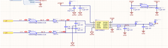
The schematic diagram is as follows:

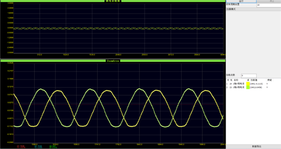
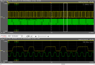
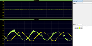
After sampling with AMC1306M25 oscilloscope test motor U phase and V phase waveform is as follows:

You can see spikes in both phases;

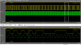
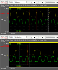
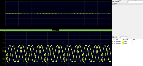
Same program and hardware, replace with AMC1204 sampled waveform:

  • Hello Kaichuan,

    Are the signals shown in the scope captures from the input? If so, can you show where the scope probes are being placed? Also, what is the frequency?

    It would also be helpful if you can explain a little bit more about the application and how the AMC is being used. 

    Regards,

    Aaron Estrada

  • Hello, I am Kaichuan’s colleague ,My name is Xiaowei. I'm the one who tests this question.The signal displayed by the oscilloscope is the code value, which is the output value of the current sampling chip.This is the upper computer's own small function, sampling frequency is 1K.This spike is not 1306M25 anti-interference ability as AMC1204.Because if you change the 1306 board to 1204, it will be normal immediately.And most of the time it happens when the current crosses zero.If it's a distraction, it's regular.And it still happens when we use copper foil to insulate the modified circuit.And we found that the smaller the motor output current, the more obvious the peak.

  • Hi Xiaowei,

    We've been talking with Dylan.  Can you provide scope captures of CLK and DATA at the controller side of the transmission for both AMC1204 and AMC1306?

  • Hi TOM Hendrick,

    CLK and DATA of 1306M25 are shown below:

    CLK and DATA of  AMC1204 are shown below:

  • Hi Xiaowei,

    Thank you for the screen shots!  Your signal integrity looks good with no obvious overshoots or ringing in either the data or clock lines.  Since your controller correctly interprets the data stream from the AMC1204, my thinking at the moment is that you are having issues with the setup and hold timing requirements on the SDFM side with the AMC1306.  From chatting with Dylan, it seems you are using a C2000 class controller, can you tell me which one you are using?  Are you running the SDFM in SYNC or ASYNC mode on the DSC?

  • Hi TOM,

        Thank you for your response.We are using TMS320F28377, we are running the SDFM in SYNC , but we use the output of PWM1 as the synchronization of SDFM data filter.You can explain how to set up asynchronous or synchronous.Is there any difference between these two for the setup and hold timing requirements on the SDFM? Looking forward to your reply.

  • Hi Xiaowei,

    I'm not an expert in the F28377, but my understanding of the SDFM module is that with ASYNC mode, you have a minimum 5nS setup and 5nS hold time with a 200MHz SYSCLK.  In SYNC mode, I believe it is 2x SYSCLK and then there is the GPIO QUAL function which acts as essentially a low-pass filter.  Your clock and data look clean, so you could try the ASYNC mode and see if there are any improvements. 

    You could also try generating a phase shifted clock to feed the SDFM from another PWM output.  For example, use ePWMx to clock the AMC1306, while ePWMy provides feedback to SD_Cx such that the rising clock edge is delayed by ~10ns to meet the timing of the AMC1306 output bit-stream. 

  • Hi Tom,

    I think if customer can change to 3-Sample Mode 0 to test the results will be much better. You can check it from following picture (Errata workarond), and this mode can also provide 2xSYSCLK set up and hold time:

    Talking about generating a phase shift clock to feed the SDFM, are you talking something like that showing below?

    Thanks!

    Dylan

  • Hi TOM Hendrick,

       Thank you for your response. This is the waveform of the C2000 receiving pin

     I measure it is 2x SYSCLK,but the waveform gets worse.

  • Yes Dylan, similar to your drawing.

  • Hi Xiaowei,

    Thank you for the added detail.  What changed from the screen shot you supplied a few days ago?  There seems to be inconsistent high times in the data stream.  If you look at the third and forth vertical division lines in the screen shot, they appear to both be a single '1' but one of them is shorter than the other.  You see that again at the 8th vertical division line.

    Are you still using the GPIO_INV function inside the controller?  Can you try flipping the polarity of the clock coming back through the LVDS transceiver instead?