Because of the holidays, TI E2E™ design support forum responses will be delayed from Dec. 25 through Jan. 2. Thank you for your patience.

This thread has been locked.

If you have a related question, please click the "Ask a related question" button in the top right corner. The newly created question will be automatically linked to this question.

XIO2001 data sheet rev D pin definition for HTQFP package

Other Parts Discussed in Thread: XIO2001

Hi!

  I got XIO2001 PNP PowerPad HTQFP in hand.

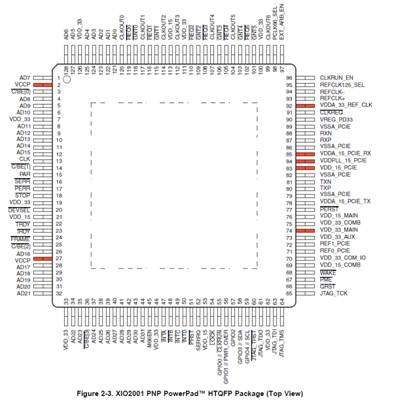
I can only get data sheet for XIO2001 Rev D. In page 14 we can find the HTQFP package. But there are no pin definition in page 15 and 16 for power supply terminal and ground terminal. We can see the pin defintion for BGA package and no information for HTQFP package.

It seems that this data sheet is modified from BGA package. The pin name in page 14 is not same as page 15 and 16.

Because the EVM is based on BGA package, so we can not have correct reference for TQFP package. Now we need to design our PCB. Please help me to get correct pin definition document in HTQFP package. Thanks!

Mike Wang

1342 Taipei 07/Apr/2011

  • Hello Mike,


    Please find attached the description for missing pins.

    Regards.

  • Elias:

      Thank you for your support. Do you have 24C02 sample code? We need to use XIO2001 with PLX PCI9030 chip for our PCIe card. Originally we have PCI9030 in our PCI card. Right now we need to have PCIe card with same software. So we use XIO2001 with PCI9030. Do you have example schematic to meet our appliation? Do we need 24C02 in this application.

    Mike Wang

    1410 Taipei 08/Apr/2011

  • Hello Mike,


    The external EEPROM can set various configuration registers but is not necessary if those register are settable via software/BIOS for the system.

    Sorry, I don't have sample code.


    Regards.

  • Dear Elias:


      Thank you for your reply. In SCPU031 (manual for XIO2001 EVM) you talk about EEPROM interface in page 6. TI recommends that we do not change the EEPROM values in EVM. Do you have EVM in hand? What is the default EEPROM value in your EVM.

      In normal PCIe card application my question is

    a) Do we need to have EEPROM for our Windows and Linux PC?

    b)Do we need to let EEPROM write protected? (READ only or READ/WRITE)

    Best Regards

    Mike Wang

    0912 Taipei  11/Apr/2011

  • Hello Mike,

    a) Do we need to have EEPROM for our Windows and Linux PC?

    Answer: No, you don't.

    b)Do we need to let EEPROM write protected? (READ only or READ/WRITE)

    Answer: No, you don't.


    Regards.


  • sorry to insist again on the question ...

    But How can I connect the GND with the PNP package ?

    it seems trivial that the Powerpad is used to connect the Gnd ...

    maybe too trivial that there is no need to mention it on the datasheet ...


    DENIS  laurent

  • Hello Denis,


    You have to connect the PowerPad to ground plane.

    Regards.

  • Hello,


    Concerning the XIO2001 in HTQFP package :

    There is no PCIR signal for this package  .  How can I set the I/O voltage (PCI rail )   to 5V ?

    For your info,  the PCI interface is   5V - 33Mhz. 


  • Hello Laurent,


    For some reason, the PCIR terminals in the HTQFP are named different, they are the VCCP (terminals 2,27)

    Regards.

  • ELIAS,

    This datasheet is highly  incomplete ….

    In red, the missing pins for the HTQFP package ..

    I don’t know how to use this pin ..


    I suppose that some of them must be connected to a filtered 1.5V , other to filtered 3.3V

    It seems that there is a internal regulator in the XIO  ,  ( cfr the pin   VREG_PD33 )

    I find no information on this chapter ..


     It is the first time I see a datasheet from TI with a so huge error …   :-(

     Could you help  ?

     Best regards,


    DENIS Laurent

  • Hi Denis,


    The below table shows the missing HTQFP (PNP) pins, with their respective equivalent with the ZAJ package and terminals description.

    Regards.

  • In the datasheet , You recommend to connect the VCCP ( PCIR )  pins  to I/O clamp rail voltage through a 1K resistor ( a  huge value) .. 

    But the schematic of your Evaluation kit does not respect this recommendation ..  ( 0 ohm to 3V3 or 5V ) ..;

    who can I  trust ?


    Thank you


    DENIS  laurent

  • Hello Denis,

    Place the 1K resistor.

    I'm going to check why the evm's schematic does not show it.

    Regards.

  • Hello Elias,

    I have a new question :


    We do not connect the 3V3AUX power supply  ( the permanent 3V3 power supply, even when the PC is down )

    from the PCIe connector to our card .

    How can I connect the  VDD_33_AUX pin of the bridge ?

    The DESCRIPTION column  of the pin mention :

    " 3.3-V auxiliary power terminal Note: This terminal is
    connected to VSS through a pulldown resistor if no
    auxiliary supply is present."


    Does it means :

     1) if the pin is left floating ( no 3V3AUX  voltage on the pin ) there is an internal pull down resistor

    2 ) if the pin is left floating ( no 3V3AUX  voltage on teh pin) , I need an external pull down resistor on hte PCB to avoid to let the pin floating.


    Is it not better to connect this pin to  (  non permanent ) 3V3 ?

    best regards,


    DENIS  laurent


  •  

    If you don't need auxiliary power, you can leave VDD_33_AUX floating.

    Regards.


  • Dear Elias:

      We have 4 PCB under test. Two PCB are working. One PCB can not let PC to power on. One PCB can work fine in first power on condition of every morning. Then we may find XIO2001 and can not find PCI device. Or we may not find XIO2001. Do you have any hint for me to find possible problem?

      In your data sheet we need to have 14532Ohm resistance between REF0_PCIE and REF1_PCIE signal (pin 71 & 72). My question is "How can we know we do not have correct resistance value between such signal pin". Or we can say "such resistance value may let something wrong". In manufacture procedure we need to find the reason for bad product. Do you have any document to help us in this resistance issue? Thanks!


    Best Regards

    MIke Wang

    1112 Taipei 24/May/2011

  • Hello Mike,


    Resistance on REF0_PCIE and REF1_PCIE are required in order to meet the PCI Express Specification.  As long as you use the resistors recommended on data sheet  you should be fine. You can simply use an ohm-meter to measure the resistance value between pin 71&72 when the system is turned off.


    If the PC is not powering up, I would look for manufacturing issues on the voltage and ground lines.

    Are you using the same PC for the working and non-working units?  If not, switch PCs in order to find some BIOS problem.

    Check that Power Up sequence listed on section 3.1 of XIO2001 data sheet is followed.

    Do you have the implementation guide? If not, find it in the below link.

    http://focus.ti.com/lit/an/scpa045a/scpa045a.pdf

    Regards.


  • Dear Elias:

    1. What is the real requirement for resistance value between pin 71 & 72. In document you specify to use 14.3K and 232ohm 1% to have 14532ohm. As we know 1% of 14.3K resistance may be 143ohm. And it is over 60% of 232ohm. So it is nonsense for 232ohm 1% requirement. Of course we can use meter to measure. But it is in factory and not in laboratary. So we need to know the phenomenon for this resistor problem. For example we may have 10Kohm in PCB or 15Kohm in PCB. How can we find such wrong condition?

    2. I use same PC and same environment to test. Now, 2 of 6 are OK and 4 of 6 are bad.

    3. We do not have 24C02 in PCB.

    4. We use LT1117-1.5 to offer 1.5V from 3.3V of PCIe slot.

    5. Do we need to use 24C02 in PCB to set some feature in XIO2001 chip?

    Best Regards

    MIke Wang

    0932 Taipei 25/May/2011

  • Hello Mike,

    1. The resistance value of 14532 ohm +/- 1% comes from setting the correct amount of current driven by TX lines to meet the PCIe specification, so even 2.32 ohm change wil have effect. Are you using just the 14.3K resistor?

    You say you have 10K in one PCB and 15K on other, is the 15K a working PCB and 10K a non-working PCB?

    2. Please describe the failure mode of each non-working PCBA.

    3. The XIO2001 can work without having an external eeprom. The external eeprom is used to set some special features of the bridge but they can be set as well from the BIOS.

    4. Looks OK.

    5. No you don't,  the XIO2001 will have basic functionality without the external eeprom.


    Can you share your latest schematics.

    Regards.