This thread has been locked.

If you have a related question, please click the "Ask a related question" button in the top right corner. The newly created question will be automatically linked to this question.

TLIN2029A-Q1: We are Getting only 1.8V in RXD Pin

Part Number: TLIN2029A-Q1

Hi,

We are using TLIN2029 in our new design.

We are sending a 1KHz signal on TXD pin of the IC. We are getting 1KHz signal on LIN Pin. We expected a 2.5V, 1KHz signal in RXD pin. But we are getting 1KHz but our voltage is only 1.8V. RXD pin is open drain output pin. We used a 10K pull up to 2.5V. 

So we are expecting a 2.5V signal on RXD.

Please help on this.

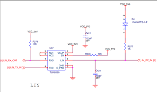
attaching the schematics

Thanks

Joseph George

  • Joseph,

    Can you share some waveforms of TXD, LIN, RXD, and the 2.5V source?

    Regards,

    Eric Hackett 

  • Hi,

    Thanks for the update.

    When i decreased pull up resistor to 2.2K, the voltage reached 2.5V in RXD pin.

    What is the maximum sink current of RXD?

    Thanks

    Joseph George

  • Joseph,

    That's strange, on both 8-pin LIN EVMs we use a 10k resistor and have no issues pulling up to the right voltage. I'll look into our characterization data for the sink current, but I don't believe that's the issue here.

    Regards,

    Eric Hackett 

  • Joseph,

    Any info on what the LIN_RX_OUT net is connected to? Some input stages, particularly certain I/O expanders, have weak biases that might pull down on the signal with something like 10 kΩ to 50 kΩ, which could help explain this behavior.

    Regarding RXD's sink strength, its minimum pull-down strength (1.5 mA) would determine the low-level voltage on RXD, which is low enough. It wouldn't impact the high-level voltage because RXD is high-impedance during a recessive signal.

    Best,

    Danny Bacic

  • Hi,

    Thanks for the update.

    Yes this signal is connected to FPGA IO pin. We have made this pin as input and we didn't given any pull up or pull down options.

    I have gone through EVK schematics also, in that pull up resistor is connected to 3.3V. In our schematics it is connected to 2.5V. But as RXD pin is open drain output it should not matter.(expecting VDS>VGS-Vth & Vgs>Vth).

    So can we make the RXD to sink 2.5mA?(Vol is Ok for us)

    Thanks

    Joseph George

  • Joseph,

    But as RXD pin is open drain output it should not matter.(expecting VDS>VGS-Vth & Vgs>Vth).

    I agree with you here. Do you have any oscilloscope measurement data that we'd be able to take a look at to try and diagnose this? When you were observing this behavior, what was the shape of the RXD signal? Did you see a relatively flat square wave, or did it appear closer to a sawtooth wave shape?

    So can we make the RXD to sink 2.5mA?(Vol is Ok for us)

    We don't have full spectrum characterization of the RXD pin across all dimensions, but what is guaranteed is that, while pulling down, if the RXD pin is held at 0.4 V, the pin will sink at least 1.5 mA to maintain that voltage. Another way to consider this is to say that, to have RXD sink 1.5 mA, you would not need to bring RXD higher than 0.4 V. In some of our testing, we would see parts with strong enough pull-down that they could sink 2.5 mA or more at 0.4 V, but there is variation between parts. The only guarantee at 0.4 V is that it can meet a 1.5 mA pull-down strength.

    If you are asking about the highest current that the pin can handle before worrying about damage, this would fall under the IO parameter of the Absolute Maximum Ratings - it can handle up to 8 mA.

    Best,

    Danny

  • Danny

    I didn't saved the oscilloscope captures, sorry. The RXD signal was sawtooth wave shape.

    If you have EVK in your premise can you also check the same giving pull up voltage to 2.5V.

    Anyway my issue is solved by decreasing the pull up resistor value, but i am interested to know the reason behind it.

    Thanks

    Joseph George

  • Joseph,

    Interesting - so it sounds like some sort of RC-related concern. The sawtooth shape is indicating to me that the high-level voltage is not becoming "steady" at 1.8 V but is rather only climbing to 1.8 V before being pulled down again.

    I don't have the ability to test this today but in the next few days I'd like to put this together as you said and see if I can replicate the behavior. I agree, it would be nice to see if we can pin down a cause to this observation. As said above, the 10 kΩ resistor on the EVM has been standard for our use cases.

    I'll follow up here once I get the chance to test this. Please also let me know if you have any additional questions in the meantime.