This thread has been locked.

If you have a related question, please click the "Ask a related question" button in the top right corner. The newly created question will be automatically linked to this question.

PCF8574: Data is not being written properly.

Part Number: PCF8574
Other Parts Discussed in Thread: MSP430F5438A

Hi,

I am using I2C3 (USCI) module as a master and PCF8574 as slave. I am using MSP430F5438A microcontroller.

I wanted to write the values of 0x08, 0x04, 0x00 to toggle the (P2, P3) port pins as per my application using run-time.

So When I give command 0x08 (P2 = 0, P3 = 1), then pins are properly configured but when I write 0x04 (P2 = 1, P3 = 0 ) or

0x00 (P2 = 0, P3 = 0) it is showing both P2 and P3 always as 1.

So 0x08 is working properly but 0x04 and 0x00 I am having issue with the device.

So I want to know why I am facing these issue. I have referred the datasheet properly but I did not found if the device is resetting or not.

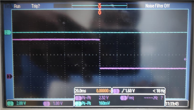
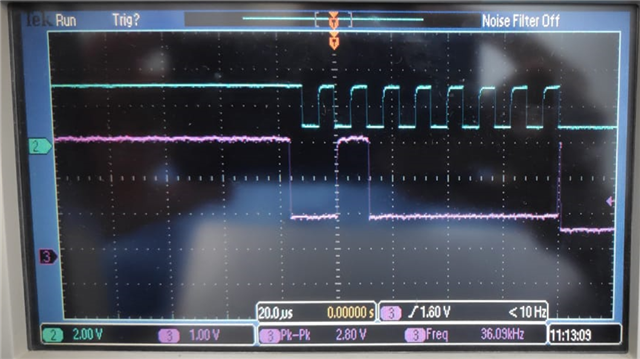
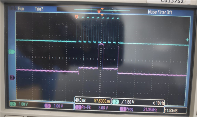
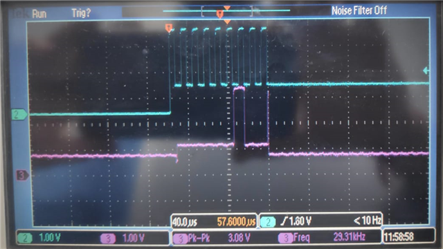
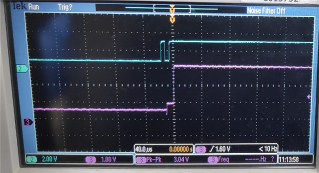
I am also getting proper waveforms for 0x04 and 0x08 on oscilloscope to ensure data transmission is proper or not.   

  • What do you mean with "showing"? Do you read through I²C, or are you measuring something?

    Please show those waveforms.

  • Actually, those (P2, P3) pins we are measuring with multi-meter.

    if IO pin is 1 then 3.3v

    if IO pin is 0 then 0v

    So if write 0x08 then we are getting P2 = 0v and P3 = 3.3v

    but for both 0x04 and 0x00 we getting P2 = 3.3v and P3 = 3.3v

  • Please show thosw waveforms.

    Do you read back the same values?

  • Madhav,

    Thanks for reaching out! In addition to Clemens's questions from above, could you clarify: Have you tried any other commands than 0x08, 0x04, and 0x00 to see if you are having other issues? If your first command after startup is 0x04, are you seeing the same issue?

    When addressing this device, please know that it does not support a repeated start command. To address this device, you will have to issue a stop command followed by a separate start command. Also, only the first data byte after the address is applied to the outputs. Make sure that you are sending the 0x08, 0x04, and 0x00 settings as totally different commands, each time addressing the device.

  • Hi Danny

    Thanks for your reply.

    After start-up whatever value I give it is working.

    Here is the I2C write code generally I am using to write any slave.

    So for PCF8574

    u8Slave = 0x20

    u8RegOffset = 0x00

     u8TxData = 0x08 ( any value from user )

    **************** I2C WRITE code *****************

    UCB3I2CSA = u8Slave;

    while (UCB3CTL1 & UCTXSTP);
    UCB3CTL1 |= UCTR + UCTXSTT;

    while(!(UCB3IFG & UCTXIFG));
    UCB3TXBUF = u8RegOffset;

    while(!(UCB3IFG & UCTXIFG));
    UCB3TXBUF = u8TxData; 

    while(!(UCB3IFG & UCTXIFG));
    UCB3CTL1 |= UCTXSTP;
    UCB3IFG &= ~UCTXIFG;

    *********************************************************************

    So every time I gave different  command my upper code will be executed.

    So, Can I say every time I am generating START and STOP condition??

  • I also found that in board start-up every thing works fine.

    but when I give command the START is not being generated means I am not seeing any High to Low transition on SDA line 

    when SCL is high.

    and If I go further I am able to see waveforms of data and STOP condition.

  • Madhav,

    Thank you for sharing your code. I am going to reach out to my colleagues that work closely with the MSP430 to see if they can offer some additional insight here regarding why a START condition isn't being generated.

    when I give command the START is not being generated means I am not seeing any High to Low transition on SDA line 

    when SCL is high.

    If the PCF8574 (or any other I2C target device) does not see a START condition, then it will not acknowledge any of the data being sent.

    We would be more easily able to help diagnose this with you if you would be able to share images of the successful and problematic I2C waveforms you are seeing on your oscilloscope. To include images, please click on "Insert" > "Image/Video/File" in your text box, as shown below:

    Best,

    Danny

  • Hi Madhav,

    This application note might be helpful as well, it addresses things to check for I2C when using MSP430 USCI: www.ti.com/lit/pdf/slaa734 The waveforms would also be helpful.

    Regards,

    Katie Pier

  • Hi

    Here are some snap I have taken while observing START, STOP . register offset and DATA waveforms.

    1. START condition

    2. Slave address (0x20)

    3) Data 1 - 0x08

    4) Data 2 - 0x04

    5) STOP condition

  • Hi Madhav,

    Can you share the rest of your code? There may be an issue with your setup.

    Thanks,

    Urica Wang

  • Hi Urica

    Below is my code.

    /* I2C3 Pins P10.1,P10.2 option select */
    P10SEL |= BIT1 + BIT2;

    /* UBC3 module configuration */

    UCB3CTL1 |= UCSWRST;

    UCB3CTL0 = UCMST + UCMODE_3 + UCSYNC; 
    UCB3CTL1 = UCSSEL_2 + UCSWRST;
    UCB3BR0 = 12;
    UCB3BR1 = 0;
    UCB3CTL1 &= ~UCSWRST;

    /* I2C write driver */

    UCB3I2CSA = u8Slave;

    while (UCB3CTL1 & UCTXSTP);
    UCB3CTL1 |= UCTR + UCTXSTT;

    while(!(UCB3IFG & UCTXIFG));
    UCB3TXBUF = u8RegOffset;

    while(!(UCB3IFG & UCTXIFG));
    UCB3TXBUF = u8TxData; 

    while(!(UCB3IFG & UCTXIFG));
    UCB3CTL1 |= UCTXSTP;
    UCB3IFG &= ~UCTXIFG

    This is same code I am using when in start-up code.

    So I start-up every value is working but when I wanted to change while run time I am having an issue.

  • If I write multiple values while booting then also it is working.

    Another observation is I have tried also values in run time through command then some values are working and some not.

    Like 20,28,24,2C values are working

    00, 04, 40, 0C are not working.

    if It is working when board boots up means my I2C configuration and write code is working fine. isn't it?

    The problem I am facing while run time only.

  • This code appears to write 2 bytes to the device, the first of which is always 0x00. As Danny pointed out, the second byte (the interesting one) is ignored [Ref data sheet (SCPS068J) Sec 8.3.1].

    I'm not quite sure I can explain all your symptoms, but what happens if you remove the write of u8RegOffset?