This thread has been locked.

If you have a related question, please click the "Ask a related question" button in the top right corner. The newly created question will be automatically linked to this question.

TRS3232E: RS232 RTS & CTS are FAIL

Part Number: TRS3232E

Dear team

The test result of FTDI RS232 RTS & CTS are FAIL.

The reasons are as follows
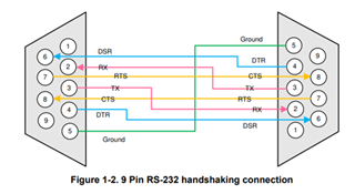
1. As shown in Figure 1, FTDI RS232 RTS hi/lo setting, I can measure the signal change at the measurement point of side A (IMX8).
But the signal change can not be measured on the test connector (B side).
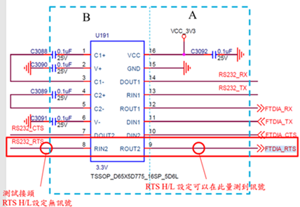
Figure 1

2. RTS is the output signal on side A (IMX8)
Compare the circuit diagram with the TRS3232E datasheet, as shown in Figure 2.
Shows that A side (IMX8) RTS is currently connected to the output terminal of TRS3232E.
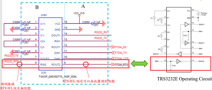
Figure 2

Conclusion :
At present, the RTS signal cannot be measured on the B side, please help to clarify, thank you

  • Denny,

    As I look into this problem, I just wanted to clarify a few things. Are the images you provided (Figure 1 and Figure 2) the same?

    I checked your external connections to the TRS3232E. All the capacitors connections and values seem to be correct when cross-referencing the datasheet. I would like to mention that the polarity of the capacitors will matter if you are using polarized tantalum or electrolytic caps. 

    Where is the RS232_RTS signal (PIN 8) coming from? Do you have oscilloscope captures of signals RIN2 (PIN8) and ROUT2 (PIN 9)? 

    I have attached a figure below showing the proper connection for RS-232 handshaking connection. Please make sure in your configuration that you have grounded your circuit properly. 

    In the question title, you say that RTS and CTS have failed. Are you seeing similar measurement inaccuracies on PIN 7 as well?

    Regards,

    -Tyler