Part Number: SN65DP141
Dear Sirs,
Please refer to the attached video for the issue.
What is the major problem for such issue? How to fix it?
Thanks.
This thread has been locked.
If you have a related question, please click the "Ask a related question" button in the top right corner. The newly created question will be automatically linked to this question.
Part Number: SN65DP141
Dear Sirs,
Please refer to the attached video for the issue.
What is the major problem for such issue? How to fix it?
Thanks.
Hi,
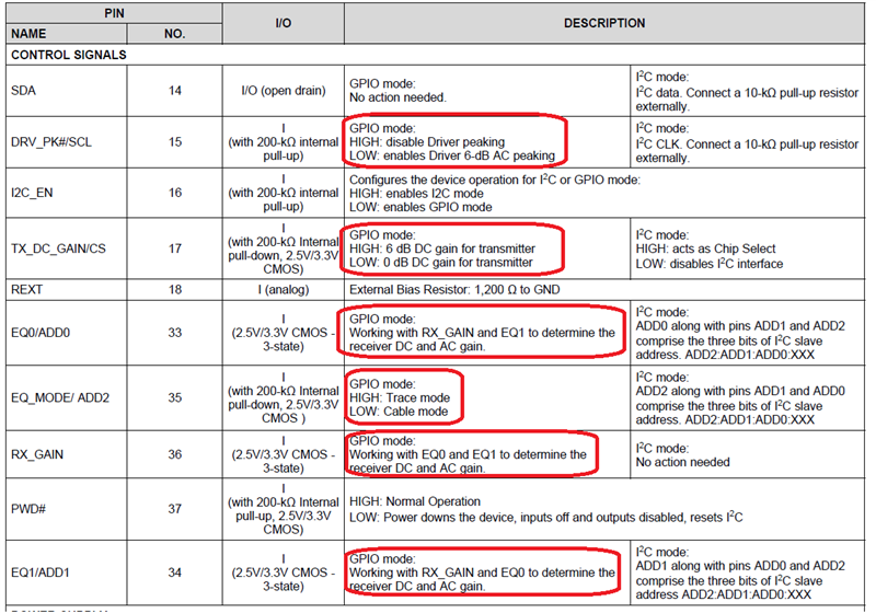
Can you send me your schematic? Also, what is the current setting for DRV_PK#/SCL, EQ_MODE, EQ0/1, RX_GAIN, TX_DC_GAIN?
Thanks
David
Hi David,
The schematics as attached.
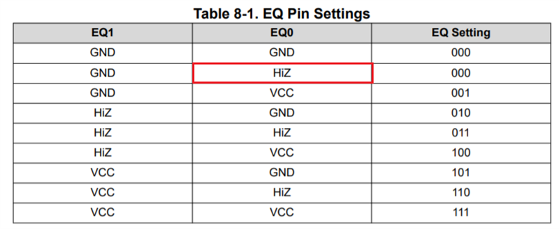
BTW, as EQ setting table, how to set the input is HiZ?

Thanks.
Hi,
Since it looks like you are connecting to a Type-C connector. For RX1/RX2, I would recommend using 0.33uF cap instead the 0.1uF.
For TX1/TX2, use 0.22uF instead the 0.1uF. Everything else looks ok in the schematic.
HiZ means leaving the pin floating.
Thanks
David
Hi David,
May I double confirm that the modification is for U9 or CN1_IN1?
Thanks.
Hi David,
Some question needs your help to check.
1. customer design will have 2 configurations, display board <--> USB-C cable <--> main board, and display board <--> main board.
May I have your suggestion about the settings of EQ_MODE & TX_DC_GAIN & DRV_PK# & RX_GAIN for both of them?
2. What's the definition of DRV_PK? And what signal will be adjusted by this pin?
3. Does TX_DC_GAIN is the output signal of pre-emphasis? What situation will choose 0dB and what for 6dB?
4. For RX_GAIN, what situation will use 0dB and what will use -6dB?
Thanks.


Hi,
When TX_DC_Gain = 0, it sets the output linearity range to 600mVpp. When TX_DC_Gain = 1, it sets the output linearity range to 1200mVpp.
RX DC Gain and EQ0/EQ1 work together to determine the best setting, please refer to Table 3 of the DP141 datasheet for the different scenario. For this particular case, you probably want to use the last 4 setting in the table.
DRV_PK adds an extra 6dB of high frequency gain. Boost happens between 6 and 10Gbps.
Do you have a high speed scope that can physically measure the DP141 output signal quality?
Thanks
David
Hi David,
Thanks for the suggestion.
About the C97~C104, since the customer use ALT mode of type C and all lanes are DP signal in fact, does customer still need to change the cap value?
Hi,
Does the main board also include caps on the TX and RX signal? I made the assumption that the main board also has caps on TX and RX, so you want to make sure the total capacitance from the display board and from the main board does not violate the spec.
Thanks
David
Dear David,
May I have your suggestion for below questions in red words?
Thanks.
1. customer design will have 2 configurations, display board <--> USB-C cable <--> main board, and display board <--> main board.
May I have your suggestion about the settings of EQ_MODE & TX_DC_GAIN & DRV_PK# & RX_GAIN for both of them?
3. Does TX_DC_GAIN is the output signal of pre-emphasis? What situation will choose 0dB and what for 6dB?
4. For RX_GAIN, what situation will use 0dB and what will use -6dB?
Hi,
For both cases, how long is the trace between the GPU and the DP141 on the main board?
Thanks
David
Hi David,
The main board data is not available since it is not handled by my customer.
For display board(AD board) and USB cable, please refer to the below chart.
This chart is for connection with USB cable.
For without cable connection, customer can connect 2 board with USB connector.
--> USB-C Cable:Max. 200cm.(there are 4 type cable: 200/100/33/2.5 cm)
--> AD Board DP Lane 0 Re-driver: 2564mil; D1 Lane 0 Re-driver: 2745mil
--> AD Board DP Lane 0 Re-driver: 1413mil; D1 Lane 0 Re-driver: 1293mil

I summary the question below, please help to give comments.
1. customer design will have 2 configurations, display board <--> USB-C cable <--> main board, and display board <--> main board.
May I have your suggestion about the settings of EQ_MODE & TX_DC_GAIN & DRV_PK# & RX_GAIN for both of them?
2. . Does TX_DC_GAIN is the output signal of pre-emphasis? What situation will choose 0dB and what for 6dB?
3. For RX_GAIN, what situation will use 0dB and what will use -6dB?
4. Please also suggest the cap value of yellow marked.
Thanks.
Hi,
1. customer design will have 2 configurations, display board <--> USB-C cable <--> main board, and display board <--> main board.
May I have your suggestion about the settings of EQ_MODE & TX_DC_GAIN & DRV_PK# & RX_GAIN for both of them?
The DP141 is a linear redriver, so we will only configure the DP141 to compensate for the loss between the Type-C plug connector and the DP141 in both cases. The SOC and the DP sink will compensate for the remaining loss through the DP Link Training. Assume 5.4G data rate, the loss for the 2.564in trace is around 1.5dB. I would try with EQ_MODE of 1, EQ_SETTING of 000 and 001, and DRV_PK# of 0.
Do you have a DP protocol analyzer that can capture the Link Training? This would really help in tuning the DP141 configuration.
2. . Does TX_DC_GAIN is the output signal of pre-emphasis? What situation will choose 0dB and what for 6dB?
No, TX_DC_GAIN set the output linearity range. I would set TX_DC_GAIN to 1 to give you the maximum linearity range.
3. For RX_GAIN, what situation will use 0dB and what will use -6dB?
RX_DC_Gain and EQ0/EQ1 work together to determine the best setting. For now, I would set RX_DC_GAIN to 0.
4. Please also suggest the cap value of yellow marked.
Between the USB-C Plug and the DP141, TX1/2 -> 0.1uF or 0.22uF. RX1/2 -> optional 0.33uF or 0.47uF. But since this is a Type-C application, the DP141 will not able to support the Type-C normal and flip orientation, so who is supporting the Type-C orientation?
Between the DP141 and the I-PEX connector, 0.1uF is ok.
Thanks
David
Dear David,
After customer test, the display issue cannot be fixed.
Did you have any suggestions for customer debug?
Below the red word is the customer feedback about the previous discussion.
1. customer design will have 2 configurations, display board <--> USB-C cable <--> main board, and display board <--> main board.
May I have your suggestion about the settings of EQ_MODE & TX_DC_GAIN & DRV_PK# & RX_GAIN for both of them?
The DP141 is a linear redriver, so we will only configure the DP141 to compensate for the loss between the Type-C plug connector and the DP141 in both cases. The SOC and the DP sink will compensate for the remaining loss through the DP Link Training. Assume 5.4G data rate, the loss for the 2.564in trace is around 1.5dB. I would try with EQ_MODE of 1, EQ_SETTING of 000 and 001, and DRV_PK# of 0.
==> the test configuration is AD board direct connected to the mainboard.
Do you have a DP protocol analyzer that can capture the Link Training? This would really help in tuning the DP141 configuration.
==> customer did not have such equipment.
2. . Does TX_DC_GAIN is the output signal of pre-emphasis? What situation will choose 0dB and what for 6dB?
No, TX_DC_GAIN set the output linearity range. I would set TX_DC_GAIN to 1 to give you the maximum linearity range.
==> already follow the suggestion but still fail.
3. For RX_GAIN, what situation will use 0dB and what will use -6dB?
RX_DC_Gain and EQ0/EQ1 work together to determine the best setting. For now, I would set RX_DC_GAIN to 0.
==> already follow the suggestion but still fail.
4. Please also suggest the cap value of yellow marked.
Between the USB-C Plug and the DP141, TX1/2 -> 0.1uF or 0.22uF. RX1/2 -> optional 0.33uF or 0.47uF. But since this is a Type-C application, the DP141 will not able to support the Type-C normal and flip orientation, so who is supporting the Type-C orientation?
Between the DP141 and the I-PEX connector, 0.1uF is ok.
==> DP/EDP main link AC cap changed to 0.1u/0.22u but still fail. AD board side was handled by PD controller.
Hi,
Having a DP protocol analyzer would help solve this issue, have they sweep through all the equalizer combination?
Thanks
David