This thread has been locked.

If you have a related question, please click the "Ask a related question" button in the top right corner. The newly created question will be automatically linked to this question.

DS90UB933-Q1: Channel Requirement clarification

Part Number: DS90UB933-Q1

Hi Team,

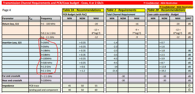
Could you please clarify the the insertion loss for Total channel requirements and Cable assembly at 15Mhz, 20Mhz, 25Mhz?.

I'm not sure If I should use the f=50Mhz number, f=10Mhz number, or assume there is a linear relationship and go somewhere in-between.

Best,

David

  • Hi David,

    The insertion loss frequency points are intended for plotting out the limit lines for total channel, pcb, and cable budgets. When plotted on a graph, insertion loss must meet total channel limit boundary (blue trace) to considered a Pass (above line) or Fail (below line).

    Regards,
    Dac

  • Hi Dac,

    Thanks very much for the feedback and graph, when my customer plotted out their insertion loss they were close to falling below the boundary between 10Mhz and 50Mhz so they wanted to clarify a few discrete points to make sure their understanding is correct.

    When I look at your graph above it appears that there is a linear relationship between the discrete points on the channel requirement document from that I calculated a few points below.

    S21 Total Channel:

    15Mhz: -2.625

    20Mhz: -2.75

    25Mhz: -2.875

    S21 Cable:

    15Mhz: -1.888

    20Mhz: -1.975

    25Mhz: -2.063

    Can you let me know if these points make sense or if I am missing something? Thanks very much for the help.

    Best,

    David

  • Hi David,

    Yes, S21 total channel and S21 cable budget insertion loss points look correct based on linear extraction. What portion of the channel limit is failing; cable or total? Cable IL shouldn't have significant attenuation at such low frequencies. 

    Regards,
    Dac

  • Hi Dac,

    It is actually the PCB that is failing at this moment:

    The current effort is to see if the entire channel still passes while the PCB fails, but I am still waiting to hear back about testing results.

    Are there any particular concerns that we should be aware of if the PCB fails but the channel as a whole passes? Seems that if the whole channel passes, the link is potentially still acceptable.

    Thanks,

    David

  • Hi David,

    The channel requirements are derived based on a pre-defined interconnect and specific budgets are allocated between cable & PCB. The cable and PCB losses can be reallocated depending on the application. Ultimately meeting the Total Channel is the normative requirement.

    Regards,
    Dac

  • Thank you very much for the help Dac.