This thread has been locked.

If you have a related question, please click the "Ask a related question" button in the top right corner. The newly created question will be automatically linked to this question.

[FAQ] DS90UB948-Q1: Input jitter tolerance

Part Number: DS90UB948-Q1
Other Parts Discussed in Thread: ALP

Hi,team

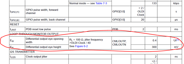
 I found only CMLOUTP/N have  describe about  input jitter tolerance , as below:

Question:

1. Is there any demand for Rin +/- about input jitter tolerence?

2. there is only typical value in the above picture, what is the max value ?

  • Hello Joey,

    RIN jitter is not something that can be measured in-situ with the system directly. Because in order to see a FC eye, you would need to disable the back channel. But if the back channel is disabled, then the FC eye margin is artificially boosted beyond what the receiver actually sees due to the BC echo cancellation. So it is not recommended to measure as part of the system qualification. Instead we recommend to qualify the channel s-parameters between the SER/DES to verify the insertion and return loss of the channel (PCB. connector, cable) to verify it is within the channel specification for the device. Additionally, we have a margin analysis tool that can be run in ALP which can show receiver margin across gain and sampler position settings. 

    CMLOUT is a band limited output which does not contain high frequency content which is seen by the FPD-Link receiver on the input side. Therefore it also does not serve as a robust way to verify exactly the receiver margin in the system. It can only be used to diagnose gross signal quality issues such as closed eye, zero crossings, or incorrect operating frequency. That is why the eye values only show typical 

    Best Regards,

    Casey 

  • Thank you for the reply,Casey

    Further questions are  :

    1 .How to judge if the Rin signal meets our minimum requirements

    2. Is there standard requirement for the insertion loss & Return loss between the SER/DES

  • Hello Joey,

    1. Use the MAP tool to check the RIN margin in-situ with the system:

    https://www.ti.com/lit/pdf/snlu243 

    https://www.ti.com/lit/pdf/snla301 

    2. Different FPD-Link device families have different channel specifications based on operating rate, device PN, etc. The channel specs can be shared under NDA. If you have a specific device pair you are interested in, please send me an email internally and we can provide you with the correct channel specification 

    Best Regards,

    Casey 

  • Hi,Casey

    Got it!

    1. We used to suggest our customer to estimate the signal chain by user MAP in the past , I asked this question is just want to get another judgement for the signal~ 

    2. If any specific case need IL& RL , at that time I will email you .

    Thank you for the help!