This thread has been locked.
If you have a related question, please click the "Ask a related question" button in the top right corner. The newly created question will be automatically linked to this question.
Below attached images has our SFP architecture.
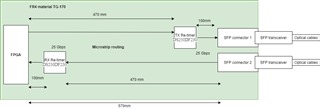
1. In Our design we are using two DS250DF230. One for TX section and another for RX section of the SFP (We are having 2 SFP ports)
As per the datasheet "It is generally recommended that channels connected to the same front-port cage be grouped together in the same DS250DF230 device" is this mandatory, With this configuration TX and RX Re-timer cannot be placed near the receiving section.
2. Can we Place the Re-timer as mentioned in the image. TX Re-timer near the SFP connector and RX Re-timer near the FPGA.
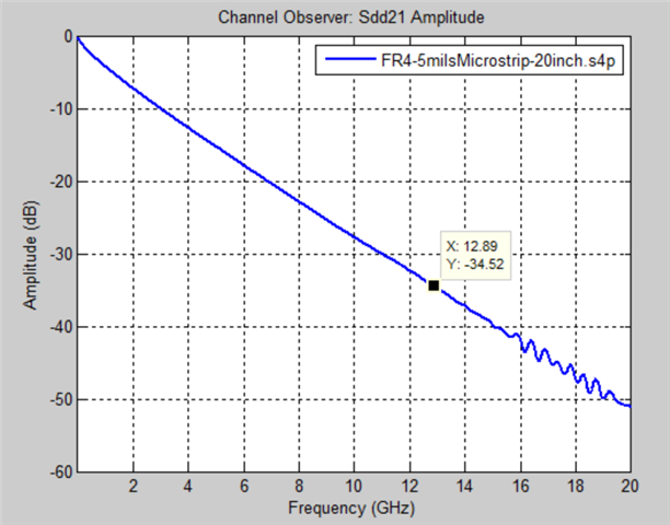
3. How to calculate the losses due the trace length. what is the formula to calculate those loses.
See my inputs below.
Thanks,
Rodrigo Natal
HSSC Applications Engineer
1. If we use 2 Retimer in TX section and 2 Retimer in RX section can we achieve this length,
2. With the above-mentioned method can we achieve 25G in FR4 TG-170 or ISOLA FR408 itself? instead of Megatron-6.
3. For such a design is there any specific layout guide that needs to be followed?
Hi, see my inputs below.
If we use 2 Retimer in TX section and 2 Retimer in RX section can we achieve this length. With the above-mentioned method can we achieve 25G in FR4 TG-170 or ISOLA FR408 itself? instead of Megatron-6.
For such a design is there any specific layout guide that needs to be followed?
See layout guidelines below.
Layout Guidelines
The following guidelines should be followed when designing the layout: