This thread has been locked.

If you have a related question, please click the "Ask a related question" button in the top right corner. The newly created question will be automatically linked to this question.

PCA9306: Asking for the level shifter PCA9306 and SN74AVC4T774 design suggestion

Part Number: PCA9306
Other Parts Discussed in Thread: SN74AVC4T774

Hi Sir,


My customer would like design PCA9306 and SN74AVC4T774 and customer need the max power information about these two device.

Would you please review the calculation and provide your comment?


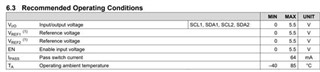
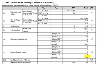
Customer use PCA9306 and SN74AVC4T774 for 3.3V to 1.8 level translation.


PCA9306 is around 0.32mW.

3.3*64=211mW

1.8*64=115mW

SN74AVC4T774 is around 244mW.

3.3*12*4=158mW

1.8*12*4=86.4mW


BR,

SHH

  • What do you mean with "power information"? The power dissipated inside the device, or the power used by the entire circuit?

    Please show the schematic.

  • Hi Clemens,

    customer need build the customer's internal part number for this part before doing schematic design.

    What is the power used by the entire circuit?

    BR,

    SHH

  • It is not possible to estimate the power usage of the entire circuit without knowing the circuit.

    The power dissipation inside the PCA9306 is negligible; what matters is the current through the 200 kΩ resistor (very little) and through the four pull-up resistors. (Multiplying the pass switch current with the supply voltage is wrong because the voltage drop over the pass switch is much smaller, and the actual current will be less than that limit.)

    The SN74AVC4T774 is a CMOS device. See [FAQ] How do I Calculate Power Consumption or Current Consumption for my CMOS Logic Device?

  • SHH,

    PCA9306:

    The internal passFET will not reach the current of 64mA because you are operating at a voltage level of 3.3V and 1.8V. The current that the passFET will see depends on the RDS_ON of the internal passFET (RDS_ON is dependent on EN voltage - Higher Vgs turns the FET on "harder") + the pullup resistances to VCC on the SDA, SCL, and Vref lines. Since the leakage on the enable pin is quite low due to impedance on the gate of the passFET, most of the current will come from what Clemens has stated: current through 200kohm, and the four pullup resistors. 

    SN74AVC4T774:

    Check out the FAQ Clemens mentioned. It is very helpful in understanding power consumption of a CMOS logic device. 

    Please let me know if you have anymore questions,

    -Tyler