This thread has been locked.

If you have a related question, please click the "Ask a related question" button in the top right corner. The newly created question will be automatically linked to this question.

DS90UB940N-Q1: I2S signal and master-slave question

Part Number: DS90UB940N-Q1

Hi team,

Now my customer has a 947-940N system and has encounter some problems.

SoC1 sends out I2S----->947----->940----->SoC2 receives I2S---->car audio equipment,

Q1. Does 947 need to configure any registers in 940N to get the I2S signal at 940N output?

Q2. Could 940N side SoC be the master and 947 side SoC be the slave? This is customer expired master-slave mode configuration and if so please tell us how to configure SER and DES to be the proper master-slave settings.

Detail descripts:

System block diagram

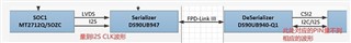
(The red words on the left mean could test the I2S signal at 947 input while the right read words mean could not test the test I2S at 940N output)

Hardware info-

947_sch.pdf

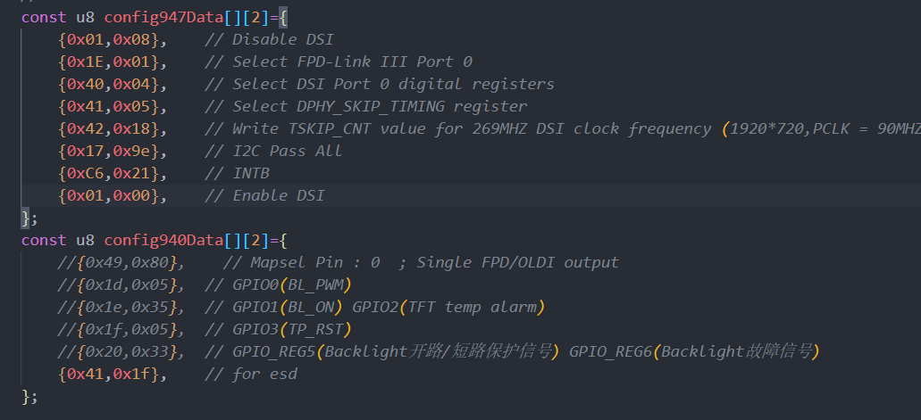
Software info- Here is the register configuration of 947 and 940N:

In my opinion it should be configured from 947 side rather than 940N side right? What other registers should be configured in 947 or 940N?

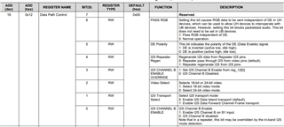
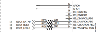
I also have questions about this 0x12 register, in our system block diagram, how could we configure this register and what does the 'I2S channel B' mean?

The 947 has already accessed the 940N so I think the LVDS link has been successfully established and besides that could we test the I2S between SER and DES?

Hope to hear from you soon, thank you.

  • Hi Jerry, 

    In my opinion it should be configured from 947 side rather than 940N side right? What other registers should be configured in 947 or 940N?

    In many cases, the I2S settings are set in registers in 947, then passed through to deserializer (via in-band I2S detection).

    Q1. Does 947 need to configure any registers in 940N to get the I2S signal at 940N output?

    For more information on programming/enabling the I2S functions, this app note is helpful in explaining the different registers and modes. 

    https://www.ti.com/lit/an/snla221/snla221.pdf?ts=1634253772821

    On 940N side, the GPIOs need to be configured as outputs. 

    Q2. Could 940N side SoC be the master and 947 side SoC be the slave? This is customer expired master-slave mode configuration and if so please tell us how to configure SER and DES to be the proper master-slave settings.

    Are you referring to the DES being the I2S master and sending audio from DES to SER? If so, this is not possible.

    This code doesn't contain any of the I2S specific register writes. Are they not modifying any of those registers directly?

    Regards, 

    Logan

  • Hi Logan

    1. Please kindly help us to list the register we should configure about 947-940N output the I2S signal;

    I have told customer to set 947 0x12 register properly and 940N GPIO 6 reg properly. Are there any other registers should we configure with 947 or 940N? They transmit the LVDS signal with I2S signal together;

    2. The I2S signal send from Local SoC to 947 to 940N to Audio device, but they need the 940N side as the master; Could 947 side be as the slave and 940N as the master? In another way to say that, could SoC (at 940N side) configure 947 register via 940N which is inverse compare to the common case (normally we should use SoC at 947 side to configure 940N register via 947) 

    If it is feasible, what should we pay attention to or could you please help to generate the related script for us to use? Thank you. 

  • Hi Jerry, 

    I have told customer to set 947 0x12 register properly and 940N GPIO 6 reg properly. Are there any other registers should we configure with 947 or 940N? They transmit the LVDS signal with I2S signal together;

    This will determine what exact I2S configuration they are trying to achieve. Can you provide overview of channel count, etc?

    The I2S signal send from Local SoC to 947 to 940N to Audio device, but they need the 940N side as the master; Could 947 side be as the slave and 940N as the master? In another way to say that, could SoC (at 940N side) configure 947 register via 940N which is inverse compare to the common case (normally we should use SoC at 947 side to configure 940N register via 947) 

    Seems like you are saying I2C master and not I2S master right? In other words, the 940 SoC will communicate over back channel to modify 947 register? This should be possible. 

    Regards, 

    Logan

  • Hi Logan,

    Yes let me clarify the application scenario:

    Customer has two application scenarios that need 947 and 940 to complete, as follows:

    I2C: SOC2 (940N side) sends touch coordinate data------>940------->947------->MCU------->SOC1; (SOC2 is the master, MCU is the slave )
    I2S: SOC1 (947 side) sends out I2S----->947----->940----->SOC2 receives I2S---->audio equipment/device;

    1. So what I mean is SoC2 at 940N side configures 947 registers via I2C; If it is possible, what registers should we configure both of 947 and 940N to do such configuration?

    2. About the I2S question, how to config 947 and 940N to successfully test the 940N I2S output since I have told customer to configure 0x12 register in 947 and what registers should we configure in 940N? They just use one channel I2S output (I2S_DA rather than I2S_DB/DC) and I have shown the schematic in this thread previously, could you please help to take a look?  

     I have also found that they wrongly configure the 940N GPIO6_REG and tell them to let it be default to be the I2S output, do you think it is right? Please help to provide us some suggestions whether there will be another registers to configure in 947 and 940N to gain the I2S output, thank you.

  • Hi Jerry, 

    1. So what I mean is SoC2 at 940N side configures 947 registers via I2C; If it is possible, what registers should we configure both of 947 and 940N to do such configuration?

    The 940 and 947 should support multi-master arbitration by default. There shouldn't need to be additional configuration needed to sent I2C writes from SoC2 side. 

    . About the I2S question, how to config 947 and 940N to successfully test the 940N I2S output since I have told customer to configure 0x12 register in 947 and what registers should we configure in 940N? They just use one channel I2S output (I2S_DA rather than I2S_DB/DC) and I have shown the schematic in this thread previously, could you please help to take a look?  

    What I2S clock rate will be used, this is one additional thing that might need configured.

    This should not take much configuration. Keep 0x12[1] set to Data Island Transport, keep 0x55 as default if TDM to parallel isn't being used. Ensuring the I2S outputs are configured as outputs in 940N.

    On 940N side, you can read in 0x28 to verify the settings are getting programmed correctly from 947.

    Regards, 

    Logan