This thread has been locked.

If you have a related question, please click the "Ask a related question" button in the top right corner. The newly created question will be automatically linked to this question.

DS90UB953-Q1: Layout suggestions for high-speed signal lines and power lines of PoC

Part Number: DS90UB953-Q1
Other Parts Discussed in Thread: DS90UB954-Q1

Hi Team,

Please help me to confirm the following question

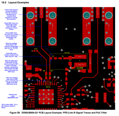
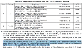
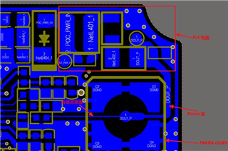
1. Does the high light mean that the layout of the PoC high-speed signal line and the power line is recommended to be on the upper and lower layers, instead of going on the same layer?
Customer are currently on the same layer (bottom), as shown in the layout diagram on the right

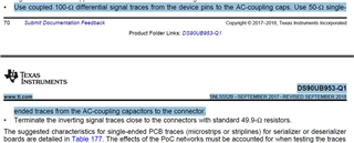
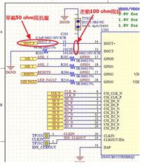
2. Does the high-light areas mean that the AC power lines shown on the below SCH are 100 ohm differential lines and 50 ohm single-ended lines?
For customer existing designs, AC ring capacitors are all tried out as 50 ohm single-ended wires

  • Hello Kygo,

    The PoC layout in the picture is going to have extremely poor high speed performance based on the routing stub from the PoC. The PoC should be attached into the high speed trace that is running to the connector from the serializer. A better layout example is shown in the DS90UB954-Q1 datasheet:

    We typically recommend to route the P/N lines loosely coupled 100 ohm differentially until they are close to the connector, and then terminate the N side near the connector at which point the P trace becomes 50 ohm single ended. 

    Best Regards,

    Casey