This thread has been locked.

If you have a related question, please click the "Ask a related question" button in the top right corner. The newly created question will be automatically linked to this question.

DP83848-EP: The PHY Ethernet generate data on RMII whereas it doesn't receive any frame

Part Number: DP83848-EP

Dears,

We encounter a problem on a custom design using the PHY Ethernet DP83848-EP.

At power on, when an Etherent cable is connected, even when the PC connected at the other side doesn't send any frame, there is a signal on RXD1 and CRC of the RMII bus.

To avoid any potential problem from external component, we have connected the PHY from one side to the transformator & connector RJ45, and to the other side (RMII), to nothing (we cut the line for tests). There are two case:

1- the PC doen't send any data (check with wireshark) -> the parasite signal is present

2- the PC send data -> our data are present with the parasite signal

It looks like we are in a failure mode.

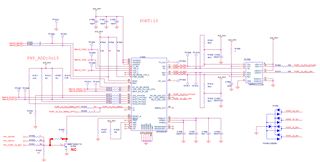
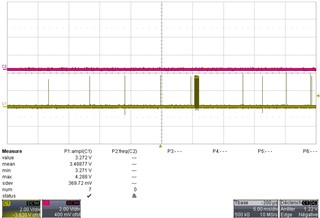
We test to change the registers without effect. We cut the MDIO line, without effect. Here is the scheme and some screenshot of the "parasite" signal.

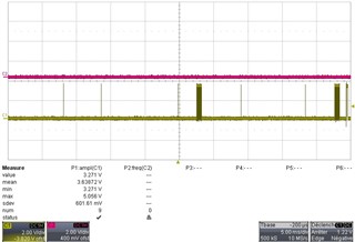
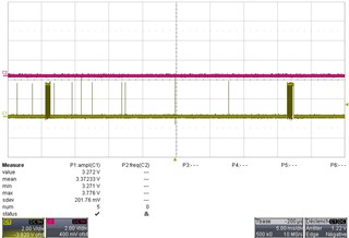
Its main characteristics are:

- there are "little communication" and "big communication"

- No period have been identified

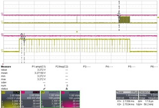
"big communication" are ~720 µs large nearly all bits are 1 and ~43 periodic bits are 0

Another interesting point is :

- when I send my data each 5 ms, I lose some unitary frame and packet of 15 frames

- when I send my data each 10 ms, I lose some unitary frame and packet of ~7 frames

- when I send my data each 2.5 ms, I lose some unitary frame and packet of 30 frames

--> the PHY seems to "sleep" sometime ~75 ms

Has anyone experiment such a problem, an idea of the mode in which we are, or a solution?

Best regards,

Benjamin

  • Hello Benjamin,

    In the bad case, are you able to read/write's PHY registers? Can you please share the values of registers 0x0 till 0x1E? May be you can dump these registers a few times to see if the PHY's status is changing.

    Also to check the power up sequence : do you know if 50MHz reference clock (on XI) is available before the PHY's supplies are up? 

    --

    Regards,

    Vikram

  • Hello Vikram,

    thanks for the answer.

    "do you know if 50MHz reference clock (on XI) is available before the PHY's supplies are up? " --> indeed the power is the same for the clock generator and the PHY. Then, during the 167 ms of PHY reset, the clock is present.

    "read/write's PHY registers" -> here are the information we get by the MDIO

    # start op phy reg ta data comment
    1 01 10 10010 00000 z0 0011 0001 0000 0000 100Mbit/s, AutoNeg, Full-duplex
    2 01 01 10010 00000 10 1011 0001 0000 0000 sw reset en + de 1.
    3 01 10 10010 00000 z0 0011 0001 0000 0000 idem 1.
    4 01 01 10010 00000 10 0010 0001 0000 0000 Autoneg off
    5 01 10 10010 00001 z0 0111 1000 0100 1001 100/10 full/half capable, preamble suppression capable, autoneg not complete, autoneg able, link not established ,ext capable
    6 01 10 10010 00100 z0 0000 0001 1110 0001
    7 01 10 10010 10000 z0 0000 0000 0000 0100 100BaseTx unconditional signal detect from PMD = 0, 100BaseTx Descrambler lock from PMD = 0, Link not established
    8 01 10 10010 10001 z0 0000 0000 0000 0000
    9 01 10 10010 10010 z0 0000 1000 0000 0000 Change of duplex interrupt
    10 01 10 10010 10100 z0 0000 0000 0000 0000
    11 01 10 10010 10101 z0 0000 0000 0000 0000
    12 01 10 10010 10110 z0 0000 0001 0000 0000
    13 01 10 10010 10111 z0 0000 0000 0010 0001 RMII mode, 2400bytes packets
    14 01 10 10010 11001 z0 1000 0000 0011 0010 Enable AutoMDIX capability, Pause_RX?, Bist fail, Led Mode 1, Phy@ 10010 ok
    15 01 01 10010 11001 10 0000 0000 0011 0010 disable AutoMDIX
    16 01 10 10010 11010 z0 0000 1001 0000 0100 Transmission of NLP is enabled, heartbeat function enabled but when device in 100Mb or full-duplex, bit is ignored, jabber function enabled
    17 01 10 10010 11101 z0 0110 0000 0001 0001
    18 01 10 10010 11111 z0 0000 0000 0000 0000

    Do you know where does this strange signal come from ? Is it a loopbak, a jabber, a test mode, a collision negociation, ..... ?

    regards,

    Benjamin

  • Hello Benjamin,

    Yes I am suspecting some corruption due to power sequence is what is causing this issue : may be loopback or some BIST is getting enabled by corruption. Do you see this issue even after toggling resetn pin? Just to isolate the problem between MAC and PHY (I hope MAC is not dumping something on these lines) : 

    1. See if you see this issue when resetn pin is held low for full time.

    2. See if you see this issue when resetn pin is held low and then released sometime after the reference clock + all supplies are fully stable.

    May be I am not reading the register log properly, but can you also share the missing registers between 0x00 to 0x1F...such as 0x00. Is  reg "10" actually register "A"?

    --

    Regards,

    Vikram

  • Hello Vikram,

    I can see this phenomenon when the initialization is stabilized  - after several seconds. Before, there is no idle on RD+/- and TX+/-, so I think the phy is not ready.

    From the mesurement, when power is up, the clk_50 Mhz (X1) arrive 1 ms after, and RESET_N is kept low during 5 secondes.


    I have difficulties to read the register by MDIO after the init (this is due to the fact that a component is in charge to setup the phy at the beginning, and is not configured to read after), but I'm working on it.

    Do you know if a false carrier could produce such a signal?

    Regards,

    Benjamin

  • Hello Benjamin,

    I went through the above thread again and I think I might have misread one point : Did you cut the MAC side connection or the MDI side connection when you still observed the noise on rx_* pins?

    And from your latest reply do you mean that you dont see rx_d1 toggling if PHY is held in reset state and reset goes high only after the clock is stable? Is it correct interpretation?

    I will check for false carrier also.

    --

    Regards,

    Vikram

  • Also can you : 

    1. re-share the snapshots you shared on your first slide with label to identify the pin of which toglling is captured.

    2.  confirm that you see toggling on rx_d1, rx_d2, rx_d3 and rx_er

    --

    Regards,

    Vikram

  • Hello Vikram,

    Here is the status and also some clarifications:

    - The board have 3 phy Ethernet. One is not use, one have the RMII & MDIO disconnected, one is connected (see CARTE.PNG)

    --> with the second PHY, we have concluded that the problem doesn't come from our component (host)

    - We can see the "strange signal" on RXD1 and CRS only. There is nothing on RXD0, RXD2, RXD3 (in RMII we don't use RXD2 and RXD3 but we have to check)

    - "do you mean that you dont see rx_d1 toggling if PHY is held in reset state" -> yes

    - "reset goes high only after the clock is stable?" -> yes that's correct

    Here are the registers status. There seems to be problem with Receive Error Latch, False Carrier Sense Latch, a RESERVED value.

    What do you think about it? Shall I change some registers values ?

    Reg00 : 2100 ok (programmed), that what we want
    Reg01 : 784D
    Reg02 : 2000 ok (datasheet)
    Reg03 : 5C90 ok (datasheet)
    Reg04 : 0101 TX_FD = 100BASE-TX Full Duplex is supported-> ok
    Protocol Selection = supports IEEE 802.3u. -> ok
    Reg06 : 0004 LP_NP_ABLE = Link Partner does support Next Page -> ??
    Reg07 : 2001 MP = Message Page -> ???
                           CODE = default value -> ok
    Reg10 : 2C05 Receive Error Latch = Receive error event has occurred since last read of RXERCNT -> PROBLEM
                            False Carrier Sense Latch =False Carrier event has occurred since last read of FCSCR -> PROBLEM
                            Signal Detect =100Base-TX unconditional Signal Detect from PMD -> ok I suppose
                             Duplex Status = Full duplex mode ->ok
                             Link Status = Valid link established (for either 10 or 100 Mbps operation) -> ok
    Reg11 : 0000
    Reg12 : 0200 FHF_INT = False carrier counter half-full interrupt is pending and is cleared by the current read -> ??
    Reg14 : 00FF FCSCNT = False Carrier Event Counter: --> PROBLEM
    Reg15 : 0004 0009 0006 000F 000A RXERCNT = RX_ER Counter: -> PROBLEM
                                                                                     When a valid carrier is present and there is at least one occurrence of
                                                                                     an invalid data symbol, this 8-bit counter increments for each receive
                                                                                     error detected. This event can increment only once per valid carrier
                                                                                     event. If a collision is present, the attribute will not increment. The
                                                                                     counter sticks when it reaches its max count.
    Reg16 : 0100 SD_OPTION = Signal Detect Option: = Enhanced signal detect algorithm -> ??
    Reg17 : 0025 RMII_MODE = Reduced MII Mode -> ok
                           RX_UNF_STS = RX FIFO Under Flow Status: Underflow detected -> ??
                           ELAST_BUF = 01 = 2 bit tolerance (up to 2400 byte packets) -> ok I suppose
    Reg18 : 0000
    Reg19 : 8031 MDIX_EN = Enable Auto-neg Auto-MDIX capability -> PROBLEM I suppose
                           LED_CNFG[1;0] = 01= Mode 1 ->ok
                           PHYADDR[4:0] = 0x11 ->ok
    Reg1A : 0904 SQUELCH = default -> ??
                           LOOPBACK_10_D IS =1 --> PROBLEM ?
                           In half-duplex mode, default 10BASE-T operation loops Transmit data
                           to the Receive data in addition to transmitting the data on the physical
                           medium. This is for consistency with earlier 10BASE2 and 10BASE5
                           implementations which used a shared medium. Setting this bit
                           disables the loopback function.
                           This bit does not affect loopback due to setting BMCR[14].
                           RESERVED = 1 !!!! Must be zero -> PROBLEM
    Reg1B : 0000
    Reg1D : 6011 ED_AUTO_UP = Energy Detect Automatic Power Up -> default
                           ED_AUTO_DOWN = Energy Detect Automatic Power Down: -> default
                           ED_ERR_COUNT =Energy Detect Error Threshold: -> default
                           ED_DATA_COUNT =Energy Detect Data Threshold: -> default

    Best regards,

    Benjamin

  • Thanks for sharing the details. I am reviewing this with the team and will get back to you. Just a few extra things I want to confirm before the review : 

    1. Cable is disconnected from RJ-45 and still you see  CRS toggling 

    2.  As you have 3 RJ-45 connectors (going to different PHYs), but are the cables connected at other 2 during this test?

    --

    Regards,

    Vikram

  • Hello,

    1. CRS toogle only when the cable RJ45 is connected (there is nothing when disconnect)

    2.There are 3 phy for a tripple redundancy. But for the tests, I connected only one of them each time 

    Regards,

    Benjamin

  • Hello Benjamin,

    To isolate the problem between 848 and other device connected on the other side of cable, can you try running BIST local external loopback as described in section 5.3.5 BIST of the datasheet. You will need to connect TX to RX using a custom cable (wire short). I will get back to you after review of the shared data with the team. 

  • Hello Vikram,

    I will manage the test as soon as possible on the 2nd of october.

    Do you think there is an incompatibility with the magnetic for example?

    Regards,

    Benjamin

  • Hello Benjamin,

    From pin-out of magnetic (shared in schematic earlier) it looks structurally ok. You may share the datasheet of magnetic and test results of loopback when available.

    I am still waiting for some further information from design team and will get back.

    --

    Regards,

    Vikram

  • Hello Vikram,

    We manage to run de BIST, but woefully the result is bad.
    Reg19 signal the test fail (bit 9 = 0) and Reg 1B signal an error counter full with BIST_CONT_MOD E = 0 or 1. Perhaps it comes from our cable or the link is the problem.

    We manage other tests by experimenting different configuration:

    Change SD_OPTION (Reg16), Change Descrambler timeout (Reg16), Change the electic buffer (Reg17), change the squelsh(reg 1A). There were no change.

    Currently, our understanding is :

    - for a reason, the phy lost synchronization (blackout during ~75 ms) 

    - Then the descrambler operate and we can see the strange signal during 2~720 µs

    If we are right, then we cant' understand why there are False Carrier Sens latch.

    Do you know where it could come from?

    I add the magnetic + connector datasheet.

    Last point, on our shematic, there is a component against ESD. Do you think it could be faulty?

    1737261.pdf

    Best regards,

    Benjamin

  • Hello Benjamin,

    This is the short week for design and other teams in TI. Hence we are taking more time to get back. You should hear back from us early next week.

    --

    Regards,

    Vikram

  • Hello Vikram,

    did you get more information from the designer team ?

    Best regards,

    Benjamin

  • Hello Benjamin,

    Inputs from our side :

    1. False carrier sense latch -> this error will happen after the link is established and there are symbol errors on the line.

    2. If loopback is also failing then the problem may not be with the link-partner or the cable. Source of signal degradation may be is on the board itself.

    To do a few checks on the board, we can check following : 

    1. Does it improve by increasing the caps on center tap of transformer to what is recommended in datasheet : 100nF + 100nF (instead of 22nF).

    2. Give 50MHz clock through a clean source (not sure about the quality of reference clock to PHY on pin XI). If the rise/fall are slower or signal integrity is poor of this clock then with any activity on the board can degrade the jitter performance of this clock further and can cause poorer link performance.

    3. Try putting 10pF of cap around Rbias resistor. (to filter any coupling to this sensitive node) 

    4. Check the placement and type of the decaps on PFBOUT, PFBIN1 and PFBIN2 (is it as per datasheet recommendation : table 3-10).

    As just looking at register reads and application changes did not help in finding the root cause, we will have to dig deeper into the electricals and noise sources on the board.

    --

    Regards,

    Vikram

  • Dear Vikram and dear all,

    Following your advice, we have finaly decided to focus our investigation on :

    - the important signal : power supply, ground, reset and clock

    - the potential defect component : RJ45 connector and magnetic, clock tree, the Phy itself and the component associated to the power supply.

    At the end, we have change the component one by one until the clock generator.

    Indeed, changing the oscillator make the signal disappear, and after making a FER, we conclude that the failure was corrected.

    So our problem was due to the oscillator that generate a sort of reset of the phy which stop receiving frame during ~75 ms, and which then generate a sort of synchronization from de descrambler (this is not documented as this but this is our understanding).

    Thanks for the help,

    Best regards,

    Benjamin