


Part Number: DP83822I
Other Parts Discussed in Thread: DP83867IR
Hello team,
I would like to confirm DP83822I LED_0 pin, LED_1 pin connection.
I would like to drive a LED using a transistor like DP83867IR datasheet figure 27 does(below).
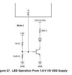
VDDIO of DP83822 is 2.5V this time, so a transistor drive is normally not needed. However, LED will be placed on different board so I would like to use a transistor to drive the LED.
- Is this connection ok for also DP83822I?
DP83822I datasheet says that LED_0 pin and LED_1 pin require parallel pull-up/down resistor.
- In case LED_1 pin is connected to base of a transistor, do we still need a parallel resistor?
LED_1 pin's bootstrap setting seems to be limited only to Mode1 and Mode4, so I would like to confirm if we can remove the parallel resistor(or boot strap resistor) in case the pin is connected to transistor's base.
Best regards,
