This thread has been locked.

If you have a related question, please click the "Ask a related question" button in the top right corner. The newly created question will be automatically linked to this question.

AM26LS31: The input of stepper motor controllor requires 5-24V, and the output of previous control circuit is only about 3.6V. How to modify the previous design?

Part Number: AM26LS31
Other Parts Discussed in Thread: SN74LVC2G17, SN74AHCT125, SN74AHCT1G125

Dear TI engineer:

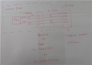
Previously, in order to connect the servo controller, CW / CCW signal about 3.6V was output by 26LS31.

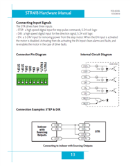
At present, I want to drive the stepper motor controller. However, the input requirements of the stepping controller are 5-24v.

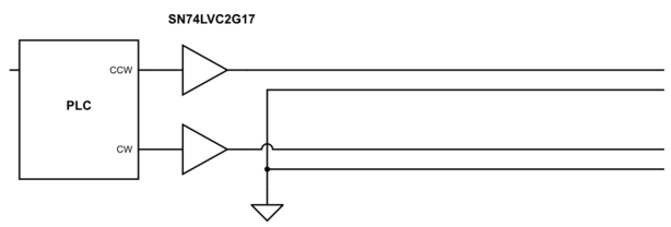
How to modify my CW/CCW circuit?

Are there some driver IC(output 5~24V) are recmmonded?

In addition, about 26LS31, there are some typical reference circuits about 26LS31 providded by Ti (capacitance abour VCC was founded. But  resistance was not founded)?

Thanks.


Regards


  • Is that 5…24 V signal differential, or not? Please tell us what motor controller you are using.

  • Dear Clemens Ladisch

    5-24V signal are single or differential(both of them are OK).

    My stepping mortor controller is STR8 made by China.

    Regards

  • These are optically isolated inputs; they do not really need a differential signal. (Or do you have a long cable between the driver and the motor controller and need high noise resistance?)

    Page 44 says that the drive strength for these inputs must be more than 5 mA at 5 V.

    If you already have 5 V signals, you might be able to connect them directly to the STR8. If your signal source is too weak, a simple logic buffer like the SN74LVC2G17 will help.

  • Dear Clemens Ladisch

    Thank you for your answer.

    I have a long cable between the driver and the mortor controller about 4 meters. 

    So differential signal should be needed, I think.

    Old control PWB has only about 3.6V signal, so this siganl should be amplified above 5V.

    Do you have some differential chips to recommend?

    Regards,

  • Forwarding to the Brushed and Stepper Motor team

    Thanks,
    Aaron

  • At each input, you have a current loop, so the signal is differential even if it is driven from logic gates. (Use a twisted pair for each +/− pair.)

    To convert from 3.6 V to 5 V, use devices with TTL-compatible inputs, e.g., 2× SN74AHCT1G125, or SN74AHCT125.

  • Dear Clemens Ladisch

    So I add  SN74AHCT125 between 26LS31 and stepping motor controller in order to amplify 3.6V to above 5V.

    The control signal flow: PLC signal - 26LS31(diffential signal) - Add SN74AHCT125( or other buffer gates) - stepping motor controller.

    Confirm please.

    Regards,

  • You do not need the 26LS31, and its output signals are not valid logic signals. What I meant to say is that you should replace the 26LS31 with the logic buffers.

    If the signals from the PCL are 5 V, you can use any 5 V buffer, e.g., the SN74LVC2G17. If the signals from the PCL are 3.3 V, then you need buffers with TTL-compatible inputs.

    You need buffers only for the + signals. The − signals can be connected directly to ground.

  • Dear Clemens Ladisch

    About current loop, I understand.Thanks.

    About logic buffer, I still have some questions.

    First, in my control PWB, I used PCL chip(PCL6143).

    Beacuse I have a long cable between the driver and the mortor controller about 4 meters. 

    So differential signal should be needed, I think.

    Differential Line Driver is not needed?

    Regards,

  • The two currents in the lines to the + pin and from the − pin have equal magnitude and flow in opposite directions. This is differential.

    A differential driver like the 26LS31 would try to make a current flow in both directions, from + to − for a high input, and from − to + for a low input. The motor controller input does not allow a current flow from − to +, so a differential driver is not necessary.

    The PCL61x3 outputs 3.3 V signals, so you need 2× SN74AHCT1G125.

  • Hello,

    I didn't find t this thread is related to a motor driver and the issue is resolved. I am going to close this thread.

    If it is not, please draw a full block diagram to show the motor and motor driver. And then, we can check your concern.

    Regards,

    Wang Li