This thread has been locked.

If you have a related question, please click the "Ask a related question" button in the top right corner. The newly created question will be automatically linked to this question.

TCAN4550-Q1: Payload extraction problem with payloads greater than 32 bytes (48 and 64 bytes)

Part Number: TCAN4550-Q1
Other Parts Discussed in Thread: TCAN4550

Hi,

I am experiencing a problem while receiving messages with payloads greater than 32 bytes. Some info:

  • Setup with three devices (MCU1 + TCAN1044, MCU2 + TCAN4550, PeakCAN in Listen mode), so I can be sure that TCAN4550 is acknowledging the message. 
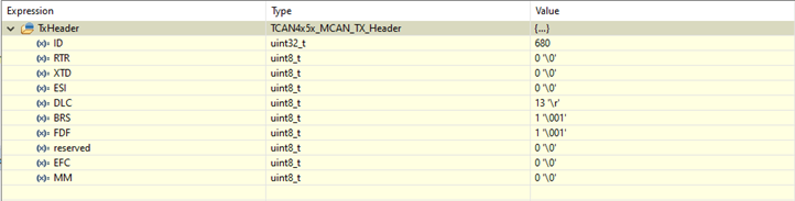
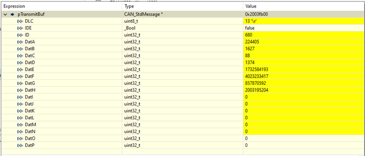
  • Tx messages are generated correctly by MCU2 + TCAN4550, even messages with 64 bytes of payload (FD + BRS) 
  • The problem consists in the payload extracted from the TCAN4550 by MCU2 being different from the payload in the message.

In the table below I list the increasingly complex PDOs I have generated from MCU1 and how they are received on MCU2: 

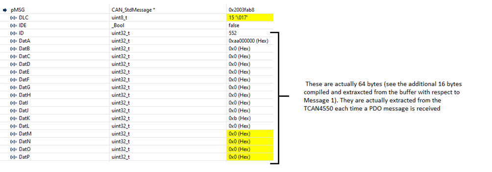
Below are the 2 messages that cannot be read. the yellow part is the change with respect to the previous message, so I'm quite confident that TCAN4550 actually received those messages, but it is failing to provide their correct content. 

Message 1 – 48 bytes wrongly received – this happens each time the PDO with CAN ID 0x228 is received (with payload of 48 bytes)

Message 2 – 64 bytes wrongly received – this happens each time the PDO with CAN ID 0x228 is received (with payload of 64 bytes)

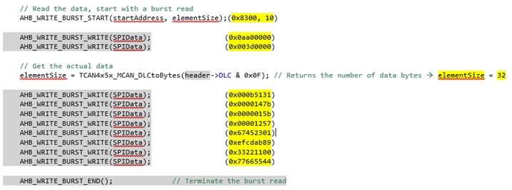
The PDO is read from FIFO RX 1, and apparently everything is working fine until I extract the payload of messages with a payload size of 48 or more.

I can see looping extracting messages from the 5 FIFO elements of FIFO RX 1, whose element size is set to 64 bytes. Message ID and DLC are correct. 

I've added the initialization code: I’m using the TCAN4550 library provided by TI.

I'm also adding the resulting configuration from the init code: 


Any idea on what could possibily go wrong ? 

/** **************************************************************************
 * @brief Init CAN peripheral.
 * @param NodeID id of the peripheral that has to be initialised
 * @return void
 ************************************************************************** */
bool CAN_enablePeripheral(uint8_t NodeID) {

    // Note : this function has been derived from the InitCAN procedure from TI code

    // local variables
	bool bSuccess = true;

    TCAN4x5x_Device_ClearSPIERR();                              // Clear any SPI ERR flags that might be set as a result of our pin mux changing during MCU startup

    // Step one attempt to clear all interrupts
	TCAN4x5x_Device_Interrupt_Enable dev_ie = {0};				// Initialize to 0 to all bits are set to 0.
	TCAN4x5x_Device_ConfigureInterruptEnable(&dev_ie);	        // Disable all non-MCAN related interrupts for simplicity

	TCAN4x5x_Device_Interrupts dev_ir = {0};					// Setup a new MCAN IR object for easy interrupt checking
	TCAN4x5x_Device_ReadInterrupts(&dev_ir);					// Request that the struct be updated with current DEVICE (not MCAN) interrupt values

	if (dev_ir.PWRON)                                           // If the Power On interrupt flag is set
		TCAN4x5x_Device_ClearInterrupts(&dev_ir);               // Clear it because if it's not cleared within ~4 minutes, it goes to sleep

	// Configure the CAN bus speeds
	TCAN4x5x_MCAN_Nominal_Timing_Simple TCANNomTiming = {0};	// 1 Mbps arbitration with a 40 MHz crystal ((40E6 / 1) / (32 + 8) = 1E6)
	TCANNomTiming.NominalBitRatePrescaler = 1;                  // Sampling point @1 Mbit/s = 32 / (32 + 8) = 80%
	TCANNomTiming.NominalTqBeforeSamplePoint = 32;
	TCANNomTiming.NominalTqAfterSamplePoint = 8;

#if CAN_FD_SUPPORT
#if CANFD_DATA_BITRATE == 8
#if CANFD_DATA_TIMING_RAW
	TCAN4x5x_MCAN_Data_Timing_Raw TCANDataTiming = {0};         // 8 Mbps CAN FD requires the raw initializer, which includes the transmitter delay compensation
	TCANDataTiming.DataBitRatePrescaler = 0;                    // 1 Syn + 1(+1) Propagation and TimeSeg1 + 1(+1) TimeSeg2 = 5
	TCANDataTiming.DataTimeSeg1andProp = 1;                     // 40E6 / 5 = 8E6 = 8 Mbit/s
	TCANDataTiming.DataTimeSeg2 = 1;
	TCANDataTiming.DataSyncJumpWidth = 1;
	// Transceiver delay compensation: tloop = 125 ns 
	TCANDataTiming.TDCOffset = 5;
	TCANDataTiming.TDCFilter = 3;
#else // CANFD_DATA_TIMING_RAW
	// Simple mode for setting
	TCAN4x5x_MCAN_Data_Timing_Simple TCANDataTiming = {0};		// 8 Mbps CAN FD with a 40 MHz crystal (40E6 / (4 + 1) = 8E6), sample point 80%
	TCANDataTiming.DataBitRatePrescaler = 1;
	TCANDataTiming.DataTqBeforeSamplePoint = 4;
	TCANDataTiming.DataTqAfterSamplePoint = 1;
#endif // CANFD_DATA_TIMING_RAW
#else
	/* Support for other bit rates */
#endif
#endif // CAN_FD_SUPPORT

    // Configure the MCAN core settings
    TCAN4x5x_MCAN_CCCR_Config cccrConfig = {0};					// Remember to initialize to 0, or you'll get random garbage!
#if CAN_FD_SUPPORT
    cccrConfig.FDOE = 1;                                        // CAN FD mode enable
    cccrConfig.BRSE = 1;                                        // CAN FD Bit rate switch enable
//  cccrConfig.DAR  = 1;                                        // Disable Automatic Retransmission (debug)
#endif

	// Configure the default CAN packet filtering settings
	TCAN4x5x_MCAN_Global_Filter_Configuration gfc = {0};
	gfc.RRFE = 1;                                               // Reject remote frames (TCAN4x5x doesn't support this)
	gfc.RRFS = 1;                                               // Reject remote frames (TCAN4x5x doesn't support this)
	gfc.ANFE = TCAN4x5x_GFC_REJECT;                				// Default behavior if incoming message doesn't match a filter is to reject for extended ID messages (29 bit IDs)
	gfc.ANFS = TCAN4x5x_GFC_REJECT;                				// Default behavior if incoming message doesn't match a filter is to reject for standard ID messages (11 bit IDs)


	/* ************************************************************************
	 * In the next configuration block, we will set the MCAN core up to have:
	 *   - n. FDCAN_nStandardFilters SID filter elements
	 *   - n. FDCAN_nExtendedFilters XID Filter element
	 *   - 5 RX FIFO 0 elements
	 *   - RX FIFO 0 supports data payloads up to 64 bytes
	 *   - 5 RX FIFO 1 elements
	 *   - RX FIFO 1 supports data payloads up to 64 bytes
	 *   - RX Buffer will not have any element, but we still set their data payload sizes, even though it's not required
	 *   - No TX Event FIFOs
	 *   - 5 Transmit buffers supporting up to 64 bytes of data payload
	 */
	/**
	 * Setup MCAN core in order to have:
	 *
	 *   - Rx filters according to the structures in the local file
	 * 	 - Rx FIFO 0 typically hosts NMT and SDO messages (up to 5 entries in the FIFO)
	 * 	 - Rx FIFO 1 typically hosts PDO messages (up to 5 entries in the FIFO)
	 */

	TCAN4x5x_MRAM_Config MRAMConfiguration = {0};
	MRAMConfiguration.SIDNumElements = FDCAN_nStandardFilters;	// Standard ID number of elements, you MUST have a filter written to MRAM for each element defined
	MRAMConfiguration.XIDNumElements = FDCAN_nExtendedFilters;	// Extended ID number of elements, you MUST have a filter written to MRAM for each element defined
	MRAMConfiguration.Rx0NumElements = 5;						// RX0 Number of elements
	MRAMConfiguration.Rx0ElementSize = MRAM_64_Byte_Data;		// RX0 data payload size
	MRAMConfiguration.Rx1NumElements = 5;						// RX1 number of elements
	MRAMConfiguration.Rx1ElementSize = MRAM_64_Byte_Data;		// RX1 data payload size
	MRAMConfiguration.RxBufNumElements = 0;						// RX buffer number of elements
	MRAMConfiguration.RxBufElementSize = MRAM_64_Byte_Data;		// RX buffer data payload size
	MRAMConfiguration.TxEventFIFONumElements = 0;				// TX Event FIFO number of elements
	MRAMConfiguration.TxBufferNumElements = 5;					// TX buffer number of elements
	MRAMConfiguration.TxBufferElementSize = MRAM_64_Byte_Data;	// TX buffer data payload size

	/* Configure the MCAN core with the settings above, the changes in this block are write protected registers,      *
	 * so it makes the most sense to do them all at once, so we only unlock and lock once                             */

	TCAN4x5x_MCAN_EnableProtectedRegisters();					// Start by making protected registers accessible
	TCAN4x5x_MCAN_ConfigureCCCRRegister(&cccrConfig);			// Enable FD mode and Bit rate switching
	TCAN4x5x_MCAN_ConfigureGlobalFilter(&gfc);                  // Configure the global filter configuration (Default CAN message behavior)
	TCAN4x5x_MCAN_ConfigureNominalTiming_Simple(&TCANNomTiming);// Setup nominal/arbitration bit timing
#if CAN_FD_SUPPORT
#if CANFD_DATA_TIMING_RAW
	TCAN4x5x_MCAN_ConfigureDataTiming_Raw(&TCANDataTiming);	    // Setup CAN FD timing (raw settings)
#else // CANFD_DATA_TIMING_RAW
	TCAN4x5x_MCAN_ConfigureDataTiming_Simple(&TCANDataTiming);	// Setup CAN FD timing (simple settings)
#endif // CANFD_DATA_TIMING_RAW
#endif // CAN_FD_SUPPORT

	TCAN4x5x_MRAM_Clear();										// Clear all of MRAM (Writes 0's to all of it)
	TCAN4x5x_MRAM_Configure(&MRAMConfiguration);				// Set up the applicable registers related to MRAM configuration
	TCAN4x5x_MCAN_DisableProtectedRegisters();					// Disable protected write and take device out of INIT mode


	// Set the interrupts we want to enable for MCAN
	TCAN4x5x_MCAN_Interrupt_Enable mcan_ie = {0};				// Remember to initialize to 0, or you'll get random garbage!
	mcan_ie.RF0NE = 1;											// RX FIFO 0 new message interrupt enable

	TCAN4x5x_MCAN_ConfigureInterruptEnable(&mcan_ie);			// Enable the appropriate registers

    CAN_initCANopenFilters(NodeID);								// Init filters

    if (bSuccess)
    {
		// Configure the TCAN4550 Non-CAN-related functions
		TCAN4x5x_DEV_CONFIG devConfig = {0};                        // Remember to initialize to 0, or you'll get random garbage!
		devConfig.SWE_DIS = 0;                                      // Keep Sleep Wake Error Enabled (it's a disable bit, not an enable)
		devConfig.DEVICE_RESET = 0;                                 // Not requesting a software reset
		devConfig.WD_EN = 0;                                        // Watchdog disabled
		devConfig.nWKRQ_CONFIG = 0;                                 // Mirror INH function (default)
		devConfig.INH_DIS = 0;                                      // INH enabled (default)
		devConfig.GPIO1_GPO_CONFIG = TCAN4x5x_DEV_CONFIG_GPO1_MCAN_INT1;    // MCAN nINT 1 (default)
		devConfig.FAIL_SAFE_EN = 0;                                 // Failsafe disabled (default)
		devConfig.GPIO1_CONFIG = TCAN4x5x_DEV_CONFIG_GPIO1_CONFIG_GPO;      // GPIO set as GPO (Default)
		devConfig.WD_ACTION = TCAN4x5x_DEV_CONFIG_WDT_ACTION_nINT;  // Watchdog set an interrupt (default)
		devConfig.WD_BIT_RESET = 0;                                 // Don't reset the watchdog
		devConfig.nWKRQ_VOLTAGE = 0;                                // Set nWKRQ to internal voltage rail (default)
		devConfig.GPO2_CONFIG = TCAN4x5x_DEV_CONFIG_GPO2_NO_ACTION; // GPO2 has no behavior (default)
		devConfig.CLK_REF = 1;                                      // Input crystal is a 40 MHz crystal (default)
		devConfig.WAKE_CONFIG = TCAN4x5x_DEV_CONFIG_WAKE_BOTH_EDGES;// Wake pin can be triggered by either edge (default)
		TCAN4x5x_Device_Configure(&devConfig);                      // Configure the device with the above configuration

		TCAN4x5x_Device_SetMode(TCAN4x5x_DEVICE_MODE_NORMAL);       // Set to normal mode, since configuration is done. This line turns on the transceiver

		TCAN4x5x_MCAN_ClearInterruptsAll();                         // Resets all MCAN interrupts (does NOT include any SPIERR interrupts)

		CAN_DriverEnable();											// Enable Hw driver
    }

	// At this step, return the status of initialization
	return (bSuccess);

} // end CAN_enablePeripheral

  • Hi Marco,

    Thanks for your detailed explanation and inclusion of data in your question. I've reviewed what you have shared here and don't see anything that would indicate an improper configuration that may cause this issue. 

    • The DLC looks to be sent and received correctly. Any receive method referencing this value should have no issue determining the payload size. 
    • The size of the RX FIFOs has been correctly configured to be 64 bytes. 
    • The MRAM configuration is an acceptable size given the available memory in MCAM (3x FIFOs/Buffer with 5x 64Byte elements each + Filters < 2kByte).

    Are you using the TCAN4x5x_MCAN_ReadNextFIFO function from the Demo code to read the FIFO data? This function takes the DLC of the header into account when reading the data. As you said, the DLC looks correct, so I don't suspect this would be the issue if this function is indeed used. Make sure that the data array passed into this function is large enough to store the expected payload. 
    If you are using a different function to read the FIFO, please share the method for our review. 

    At which point in the program are you pausing to review the contents of the received data? If you are using a debug mode, can you step into the receive function to see each set of bytes being extracted from the FIFO? I would like to see if the first bytes come through correctly (as they would for <33Bytes) and possibly get corrupted later. 

    Regards,
    Eric Schott

  • Hi Eric, thanks for your reply : I'll follow your advice and get back to you with the results. 

    In the meanwhile I discovered that I actually do have a problem also when transmitting. I'm adding the explanation in the main post

  • I actually discovered that I have a problem also when transmitting, and even with payload of 32 bytes: 

    At a certain point I am calling the function TCAN4x5x_MCAN_WriteTXBuffer: 

    The parameters to this function are displayed below: 

    I am following the actual write operations to the controller, as displayed below: 

    But I end up with the following message transmitted, where the last 4 bytes have no connection with the programmed output: 

  • Hi Eric, thanks again for your support. Here some answers to your questions: 

    • I'm using a slightly modified version of the TCAN4x5x_MCAN_ReadNextFIFO, but the modifications should not pose any threat (I'm attaching it for reference anyway - look for "ABB" to detect variations from the original version) .
    • The array where the payload is to be stored is big enough (a 64-byte message) for the expected payload
    • by debugging step-by-step I can see that in case of 48-byte and 64-byte messages data are corrupted directly from the SPI read operation

    The examples below show what i rear or write from SPI (in yellow) in a case where the message is working (payload = 32 bytes) or not working (payload = 48 bytes)

    Message with 32 bytes payload

    Message with 48 bytes payload

    It can be seen that the SPI read operations already fail in giving back the expected content based on the received PDO.

    Additionally, they always return the same value.

    This is in line with what I see from the debugger at the calling function (once returned from the TCAN4x5x_MCAN_ReadNextFIFOFromFilter)

    uint8_t
    TCAN4x5x_MCAN_ReadNextFIFO_FromFilter(TCAN4x5x_MCAN_FIFO_Enum FIFODefine, TCAN4x5x_MCAN_RX_Header *header, uint8_t dataPayload[], uint32_t CANopenFilterType)
    {
        uint32_t readData;
        uint16_t startAddress;
        uint8_t i = 0, getIndex, elementSize;
    
        // Get the get buffer location and size, depending on the source type
        switch (FIFODefine)
        {
            default: // RXFIFO0 is default
            {
                readData = AHB_READ_32(REG_MCAN_RXF0S);
                if ((readData & 0x0000007F) == 0)
                    return 0;
                getIndex = (uint8_t) ((readData & 0x3F00) >> 8);
                // Get the RX 0 Start location and size...
    #ifdef TCAN4x5x_MCAN_CACHE_CONFIGURATION
                readData = TCAN4x5x_MCAN_CACHE[TCAN4x5x_MCAN_CACHE_RXF0C];
    #else
                readData = AHB_READ_32(REG_MCAN_RXF0C);
    #endif
                startAddress = (uint16_t)(readData & 0x0000FFFF) + REG_MRAM;
    #ifdef TCAN4x5x_MCAN_CACHE_CONFIGURATION
                readData = TCAN4x5x_MCAN_CACHE[TCAN4x5x_MCAN_CACHE_RXESC];
    #else
                readData = AHB_READ_32(REG_MCAN_RXESC);
    #endif
                readData &= 0x07;
                elementSize = TCAN4x5x_MCAN_TXRXESC_DataByteValue(readData); // Maximum theoretical data payload supported by this MCAN configuration
                // Calculate the actual start address for the latest index
                startAddress += (((uint32_t)elementSize + 8) * getIndex);
                break;
            }
    
            case RXFIFO1:
            {
                readData = AHB_READ_32(REG_MCAN_RXF1S);
                if ((readData & 0x0000007F) == 0)
                    return 0;
                getIndex = (uint8_t) ((readData & 0x3F00) >> 8);
                // Get the RX 1 Start location and size...
    #ifdef TCAN4x5x_MCAN_CACHE_CONFIGURATION
                readData = TCAN4x5x_MCAN_CACHE[TCAN4x5x_MCAN_CACHE_RXF1C];
    #else
                readData = AHB_READ_32(REG_MCAN_RXF1C);
    #endif
                startAddress = (uint16_t)(readData & 0x0000FFFF) + REG_MRAM;
    #ifdef TCAN4x5x_MCAN_CACHE_CONFIGURATION
                readData = TCAN4x5x_MCAN_CACHE[TCAN4x5x_MCAN_CACHE_RXESC];
    #else
                readData = AHB_READ_32(REG_MCAN_RXESC);
    #endif
                readData = (readData & 0x70) >> 4;
                elementSize = TCAN4x5x_MCAN_TXRXESC_DataByteValue(readData); // Maximum theoretical data payload supported by this MCAN configuration
                // Calculate the actual start address for the latest index
                startAddress += (((uint32_t)elementSize + 8) * getIndex);
                break;
            }
        }
    
    
        // Read the data, start with a burst read
        AHB_READ_BURST_START(startAddress, 2);
        readData = AHB_READ_BURST_READ(); // First header
        header->ESI = (readData & 0x80000000) >> 31;
        header->XTD = (readData & 0x40000000) >> 30;
        header->RTR = (readData & 0x20000000) >> 29;
    
        if (header->XTD)
            header->ID  = (readData & 0x1FFFFFFF);
        else
            header->ID  = (readData & 0x1FFC0000) >> 18;
    
        readData = AHB_READ_BURST_READ();   // Second header
        AHB_READ_BURST_END();               // Terminate the burst read
        header->RXTS    = (readData & 0x0000FFFF);
        header->DLC     = (readData & 0x000F0000) >> 16;
        header->BRS     = (readData & 0x00100000) >> 20;
        header->FDF     = (readData & 0x00200000) >> 21;
        header->FIDX    = (readData & 0x7F000000) >> 24;
        header->ANMF    = (readData & 0x80000000) >> 31;
    
        /* ABB code start - Stucchi Marco - 5 March 2021 */
    
        // Check if the message comes from a message with the correct Filter Type.
        // On that case continue with the message extraction, otherwise return, leaving the message in the controller from the correct entity
        if ((header->ANMF != 0) ||
       		(CANopen_GetFilterType(header->XTD == 0, header->FIDX) != CANopenFilterType))
        {
        	// Message not from the indicated filter: quit leaving the message in the peripheral
        	return 0;
        }
    
        /* ABB code end */
    
        // Get the actual data
        // If the data payload size of the header is smaller than the maximum we can store, then update the new element size to read only what we need to (prevents accidental overflow reading)
        if (TCAN4x5x_MCAN_DLCtoBytes(header->DLC) < elementSize )
            elementSize = TCAN4x5x_MCAN_DLCtoBytes(header->DLC); // Returns the number of data bytes
    
        // Start a burst read for the number of data bytes we require at the data payload area of the MRAM
        // The equation below ensures that we will always read the correct number of words since the divide truncates any remainders, and we need a ceil()-like function
        if (elementSize > 0) {
            AHB_READ_BURST_START(startAddress + 8, (elementSize + 3) >> 2);
            i = 0;  // Used to count the number of bytes we have read.
            while (i < elementSize) {
                if ((i % 4) == 0) {
                    readData = AHB_READ_BURST_READ();
                }
    
                dataPayload[i] = (uint8_t)((readData >> ((i % 4) * 8)) & 0xFF);
                i++;
                if (i > elementSize)
                    i = elementSize;
            }
            AHB_READ_BURST_END(); // Terminate the burst read
        }
        // Acknowledge the FIFO read
        switch (FIFODefine)
        {
        default: // RXFIFO0
            AHB_WRITE_32(REG_MCAN_RXF0A, getIndex);
            break;
    
        case RXFIFO1:
            AHB_WRITE_32(REG_MCAN_RXF1A, getIndex);
            break;
        }
    
    
        return i;   // Return the number of bytes retrieved
    }
    

  • Hi Marco,

    Thanks for the extra information. I'm looking into this and will get back to you with an update tomorrow. 

    Regards,
    Eric Schott

  • Marco,

    We're still looking into this, thank you for your patience.

    Regards,

    Eric Hackett 

  • Hi Eric, please let me know if I can provide you with some additional data to help your investigation..

    Thank you,

     Marco

  • Hi Marco,

    Thanks for your patience on this.

    I think this may have to do with the format of the data array you are using. Each of these functions to read and write to the data portion of buffers/FIFOs expcets the array to be a uint8_t pointer. The pointer used for for pTransmitBuf is to a uint32_t object. This works fine as the relative position of everything is fine and there's no real casting being done. However, the pointer math for these two types is different. We only start to do pointer math after a certain number of iterations through the data, so this would only impact cases where larger payloads are used. 

    Can you try calling these methods with a uint8_t pointer object? It is likely fine to cast the currently used pointer to a smaller value so that the pointer math done in each of these functions can provide the correct offsets. 

    Let me know if this helps. If not, there are a few other tests I can run to see if I can recreate this on my setup. 

    Regards,
    Eric Schott

  • Hi Eric,

    Thank you for your suggestion, even if I don't understand how the proposed modification could help in solving the problem. As per my understanding, in fact:  

    1. the caller is in charge of passing the correct parameter,
    2. the callee is in charge of working on the passed parameter. TI's function, expecting to work on an unsigned char pointer, will apply the correct arithmetic on the passed parameter, assuming it is of the correct type

    As you mentioned, an array of uint32_t objects can be filled by using a pointer to uint8_t, and the actual instructions on the pointer are carried out by TI's functions, which assume that the passed parameter has the correct type. This fact should make pointer arithmetic work as expected. Additionally, the passed parameter, even if of a different type (uint32_t * vs uint8_t *)  points to the beginning of the buffer.

    So, the fact that I use an array of 16 adjacent uint32_t objects is equivalent to have an array of 64 uint8_t objects, as far as TI's functions are concerned. 

    However, I tried to cast the passed parameter as advised,

    TCAN4x5x_MCAN_WriteTXBuffer(txqfsRegister.TFQP, &TxHeader, (uint8_t *)&(pTransmitBuf->DatA));

    but, apart from removing the compiler warning on the type, the compiled code does not change at all. In fact, when trying to download the newly compiled code to the target, I get the message below:  

    CMD>VM
    Verifying.
    Verified.
    Application verified in memory. No need to reprogram.

    Thank you,

     Marco

  • Hi Marco,

    Apologies for the inaccurate suggestion. I am primarily an expert in the electrical characteristics of our transceivers and it seems you may have more knowledge regarding the C programming used here. 

    As I have not encountered this type of behavior before with other customer reports or my own testing the TI's demo code, I don't believe this is caused by the device itself or the demo inherently. It is likely having to do with the interactions between the demo code and the unique software written for this application. I have been unable to identify this undesired interaction through my review of this code and it seems that you may out qualify me for such investigations. As software support is not a primary focus of this forum, I don't believe there is much more I will be able to contribute to this thread from a review standpoint.

    Is there any device-specific information I can help provide to help resolve this issue?

    Regards,
    Eric Schott