This thread has been locked.

If you have a related question, please click the "Ask a related question" button in the top right corner. The newly created question will be automatically linked to this question.

DP83867IR: Zynq 7000 PSMIO RGMII 1G TX error

Part Number: DP83867IR
Other Parts Discussed in Thread: MIO

Hello everyone,

We have a new project that uses Xilinx Zynq 7000 (XC7Z010) processing logic RGMII driver connected to DP83867IRRGZ PHY. 

We use this combination in few other projects as well. However in the new project there is (I believe) a problem with the RGMII interface.

This problem is related only to 1G (RGMII). 100M (RMII) always works well.

There are also 2 DP83867IR's on the board fed from the PL (FPGA) part of the Zynq which always work at 1G without any problem.
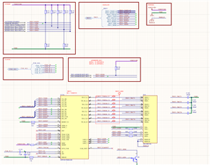
We receive valid data from the outside PHY3_RXDx, but transmitted data caught by the wireshark are not valid. There is some random data only. Thus I 

suspect RGMII TXD part of the interface is not working correct. 

Some basic facts about the PCB:

1) Zynq connected to 3 identical PHY's DP83867IRRGZ

2) PHYs on the PL are working at 1G no problem

3) PHY on PS part works at 100M no problem, but at 1G not working

4) We have different boards with similar configuration where PS PHY works at 1G. But there are shorter RGMII traces. Similar stackup.

5) RGMII traces are routed at 50ohms (+-10%) impedance profile. This is provided by Simbeor plugin of Altium. Vias are also calculated to 50ohms.

6) RGMII traces are length matched. TX group length is 58.8mm (+-0.1mm), RX group length is 56.3 (+-0.05mm). 

7) All RGMII signals are routed on the layer 3 of the 10 layer PCB. Zynq is on L1, PHY on L10. L2 is a huge ground plane to provide solid return path.

8) The RGMII traces are routed from the ball of the Zynq BGA on L1 to L3, then continue in L3 close to PHY, goes through via to L10. Then connects to the PHY:
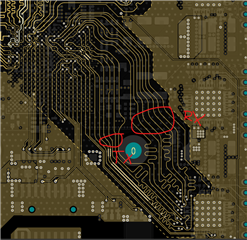
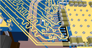
9) We tried to route the traces as far of each other as possible to minize crosstalk. There are no series nor parallel termination resistors.

10) General rule of thumb is 6 inch max for RGMII. We are one third roughly so length should be OK. However it might not be true as on our similar board with PHY3 closer to the Zynq 1G works.

11) PCB Stackup - 10layer
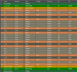
12) MDI is not the problem as exactly the same layout is used on the 3 PHYs (and those 2 on PL work well at 1G):
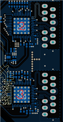
13) No matter which combination of PS MIO speed (slow/fast) PU/PD on Zynq and RGMII delay on PHY we use. It never works correctly.

14) We even tried terminating the RGMII TX line (TXD1,2,3,4, CLK) at the end - near PHY with parallel termination resistors (120R, 100R, 49,9R). Nothing helped

15) Using 200MHz scope we are able to see some data on the RGMII lines, so it is not completely dead. However it does not have enough bandwidth to do deeper research.

Do you have any suggestions what could help?

Thank you.

  • Hi Vaclav,

    Thank you for your query. I will bring this up to the team for discussion. I expect a response by Wednesday at the latest.

    Sincerely,

    Gerome

  • Hi Vaclav,

    The only suggestion I have is to check the signal integrity of the TXD signals. This would entail a scope with higher bandwidth than what is currently being used. You had said that RXDX data is valid. Is this from the scope or another utility (like Wireshark)?

    Sincerely,

    Gerome

  • Hi Gerome,

    Thanks for your answer. Yes we should buy som better scope to check the real world signals. About the RXD direction. We use another system on LAN to send message to the port (PHY3) and check whether Arm in Zynq receives valid data including CRC. It does. We check the TX direction in the similar manner. Send data from Arm core and verify (wireshark and/or our system) data validity. We also tried to connect PHY2 and PHY3 between each other. Then the transmitted data from the Arm on PHY3 goes through PHY2 to chipscope in the FPGA. Both tests result in broken data and CRC fails.

    Best regards,

    Vaclav

  • Just clarifying, PHY3 is the PHY on PS which is having RGMII issues, but not RMII issues while PHY1 and PHY2 are the ones on PL? Can you also expand on what these acronyms mean?

    Sincerely,

    Gerome

  • PHY3 is the one on PS = processing system = ARM = MIO PINS. The other two (PHY1 and PHY2 are on PL - programmable logic - FPGA pins). 

  • Hi Vaclav,

    Outside of scoping, the only other debug step I can help with is to simulating using the IBIS model of DP83867 along with and IBIS model of the ARM (traces included) and see if you see high skew between data and clock.

    The model is available here: www.ti.com/.../snlm191

    Sincerely,

    Gerome

  • Hello Gerome,

    I already did some IBIS simulations before asking here. I used original Xilinx XC7Z pin IBIS, DP83867 ibis directly from TI and lossy transmission line with parameters from Altium/Simbeor. The conclusion is that it seems ok even without any line termination added. Serier termination dampens some oscillations. But there is no way I can add series resistors to the signals at the driver as it starts under the BGA and goes through internal layer of the PCB. I guess the only way is to use proper scope. I'm working on it. I will let you know as soon as I get any results.

    Thanks for now.

    Vaclav

  • Vaclav,

    Thanks for the update. I look forward to hearing your findings.

    Sincerely,

    Gerome