


Part Number: DP83822I
Hello,
In DP83822I PHY Two types of LED_0 driving connections are possible,
1. LED_0 Pin in Sink mode - Pull-Up Configuration
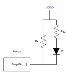
2. LED_0 Pin in Source mode - Pull-Down Configuration

Which configuration is recommended as per TI?
Part Number: DP83822I
Hello,
In DP83822I PHY Two types of LED_0 driving connections are possible,
1. LED_0 Pin in Sink mode - Pull-Up Configuration
2. LED_0 Pin in Source mode - Pull-Down Configuration
Which configuration is recommended as per TI?
