This thread has been locked.

If you have a related question, please click the "Ask a related question" button in the top right corner. The newly created question will be automatically linked to this question.

DS90UB953-Q1EVM: Analog LaunchPAD cannot communicate with DS90UB953

Part Number: DS90UB953-Q1EVM
Other Parts Discussed in Thread: ALP

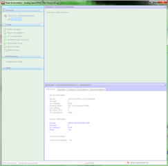
I am attempting to use the DS90UB953-Q1EVM to verify the FPD-Link III interface on another board.  When I load Analog LaunchPAD and configure it for a DS90UB953, it becomes slow and unresponsive; in addition, I seem to be unable to read the registers.  It reports the device address as being 0x00.  According to the manual, If the value is 0x00 instead of 0x30, you need to switch the
profiles for the assigned USB ID and re-verify the Device ID.  However,I cannot see any instructions on how to do this.  I have attached a screenshot showing the problem.

  • Hello,

    It sounds to me like the device is not powered.  It should be configured initially out of the box for PoC but if you are using it locally without talking through a deserializer then you will need to power the device locally.  Are you using a deserializer? What are you trying to setup here?

    Regards, 

    Nick

  • I have connected it to a board that we are developing that has a DS90UB964 deserialiser.  I have checked the link between the two boards with a scope and I can see 5V with the signal overlaid.  However, when I probe the PoC connector on the board, I do not see a Voltage.

  • I have found a problem with the power settings on the board with the deserialiser; I have fixed this and I can now access the registers on the UB953.  However, it reports the Partner Device as an "UNKNOWN DESERIALIZER".  The application contains a device profile for the DS90UB964; should it not detect said device?

    Also, is 5V enough for PoC?  The manual mentions >=7V.

  • Hi Stephen,

    You will need to make sure you have the ALP profiles for both the device you are connected to and the remote device.  Also is there a specific reason why you are connecting directly to the SER?  It may be easier to connect to the DES and talk to the device over FPD-Link.

    Also Any PoC voltage should work, you just want to make sure the power getting to the device is good.

    Regards,

    Nick

  • Mu understanding is that the DS90UB953 needs to be configured for the correct speed before the DS90UB964 can detect it over FPD-Link III.  Is this not the case?  I have run i2cdetect on the I2C bus containing the DS90UB964's remote interface (the DS90UB964 is hosted on a SBC running Linux) and it is not seeing the serialiser, which I believe should be visible at address 0x18.

    Is there anything that I should know about using the DS90UB953 and DS90UB964 together?  The datasheet seems to indicate that an external clock is required; I have fitted R1 to the EVM to connect the oscillator to CLKIN and configured register 0x03 for DVP External Clock Backward-Compatible Mode. 

    The purpose of the current exercise is to verify that the FPD-Link III interface on the SBC is working.  Is my approach flawed in any way?

  • Hi Stephen,

    The 953 does need to be configured to be paired with the 964, but this can be done by setting the appropriate strap value on the mode pin so that it is configured at startup.  If you are using the 953 EVM you can set this with jumper J8.  An external clock is only required if you plan to use non-sync mode, otherwise the 953 will derive it's clock from the 964 back channel.

    Can you elaborate on the SBC and what you are trying to prove? Or are you just trying to see LOCK?  I think your approach can work but we need to make sure both devices are configured correctly.

    Regards,

    Nick

  • The SBC is a Jetson carrier board designed by my employer; the aim at the moment is to verify that all of the electrical interfaces are working.  The design features the DS90UB960 but since the part is not currently available, we have had to substitute a DS90UB964.

    So far, I have been able to confirm that I can receive the colour bar pattern generated by the DS90UB964 on the Jetson's MIPI bus.  We had hoped to confirm that the FPD-Link III interface was working by capturing from a D3RCM-OV10640-953 camera but I was unable to see this on the I2C bus.  My manager decided that the next step would be to try the DS90UB953-Q1EVM to see whether programming the DS90UB953 directly would enable me to establish communications.

  • Are you trying to communicate with a sensor on the 953 side with I2C? If so, then you need to set up the I2C ID and ALIAS registers in the 964 to be able to pass I2C data over FPD-Link.

    Regards,

    Nick

  • I don't currently have a sensor on the 953; the current aim is to verify whether I can talk to the 953 from the 964 over I2C.  Note that since the SBC is still in the prototype phase, it's entirely possible that there is an electrical problem.

    According to the schematics and the datasheet, fitting a jumper to J8 would put it into CSI-2 Synchronous mode, which I believe isn't supported by the 964.  Would I need to remove R12 and put a different value across J8?

  • Hello,

    I don't think this is an electrical issue, I feel it is probably just a configuration issue.

    Setting the device to CSI mode is fine, just need to make sure that the both the serializer and deserializer are configured to the same mode.  Can you pull the registers from each device so I can check your configuration?

    Regards,

    Nick

  • Sorry for not getting back to you sooner; I've been sidetracked with other projects the last couple of weeks. 

    This is the output from i2cdump on the SBC with the DS90UB964:

         0  1  2  3  4  5  6  7  8  9  a  b  c  d  e  f    0123456789abcdef
    00: 7a 00 1e 30 c2 01 00 fe 1c 10 79 79 03 b0 f9 ff    z.?0??.???yy???.
    10: 00 00 00 13 00 00 00 00 01 61 a8 e3 dd 00 04 04    ...?....?a???.??
    20: 00 03 00 03 81 00 00 00 00 00 00 00 00 00 00 00    .?.??...........
    30: 00 00 00 42 00 00 00 10 00 00 00 00 00 00 00 00    ...B...?........
    40: 00 a9 71 01 00 00 00 00 00 00 00 00 00 30 22 02    .?q?.........0"?
    50: 15 00 00 02 00 00 00 00 58 00 00 30 00 30 64 00    ?..?....X..0.0d.
    60: 00 00 00 00 00 84 24 00 00 00 00 00 00 7f 8a 88    .....?$......???
    70: 2b 2c 00 00 00 00 00 c5 00 01 00 00 00 00 00 00    +,.....?.?......
    80: 00 00 00 00 00 00 00 00 00 00 00 00 00 00 00 00    ................
    90: 00 00 00 00 00 00 00 00 00 00 00 00 00 00 00 00    ................
    a0: 00 00 00 00 00 00 00 00 00 00 00 00 00 00 00 00    ................
    b0: 1c 13 1f 08 25 00 18 00 f8 33 03 74 80 00 00 00    ????%.?.?3?t?...
    c0: 00 00 00 00 00 00 00 00 00 00 00 00 00 00 00 00    ................
    d0: 00 43 84 02 60 f2 00 07 00 01 05 03 00 00 00 00    .C??`?.?.???....
    e0: 00 00 00 00 00 00 00 00 00 00 00 00 00 00 00 00    ................
    f0: 5f 55 42 39 36 34 00 00 00 00 00 00 00 00 00 00    _UB964..........

    This is the dump from Analog Launchpad on the DS90UB953-Q1EVM:

    [REGISTERS]
    Device = ALP Nano 1 - DS90UB953, Connector 1
    Comments = ""
    Date = 11/29/2021
    Time = 09:22:46
    Reg = 0,0x0000,0x30
    Reg = 0,0x0001,0x00
    Reg = 0,0x0002,0x33
    Reg = 0,0x0003,0x5D
    Reg = 0,0x0004,0x00
    Reg = 0,0x0005,0x03
    Reg = 0,0x0006,0x41
    Reg = 0,0x0007,0x28
    Reg = 0,0x0008,0xFE
    Reg = 0,0x0009,0x1E
    Reg = 0,0x000A,0x10
    Reg = 0,0x000B,0x7F
    Reg = 0,0x000C,0x7F
    Reg = 0,0x000D,0xF0
    Reg = 0,0x000E,0x0F
    Reg = 0,0x0010,0x00
    Reg = 0,0x0011,0x00
    Reg = 0,0x0013,0x00
    Reg = 0,0x0014,0x00
    Reg = 0,0x0015,0x20
    Reg = 0,0x0017,0x3C
    Reg = 0,0x0018,0x80
    Reg = 0,0x0019,0x62
    Reg = 0,0x001A,0x62
    Reg = 0,0x001B,0x62
    Reg = 0,0x001C,0x00
    Reg = 0,0x001D,0x00
    Reg = 0,0x001E,0x00
    Reg = 0,0x0020,0x00
    Reg = 0,0x0021,0x00
    Reg = 0,0x0022,0x00
    Reg = 0,0x0023,0x00
    Reg = 0,0x0024,0x00
    Reg = 0,0x0031,0x20
    Reg = 0,0x0032,0x49
    Reg = 0,0x0033,0x04
    Reg = 0,0x0035,0x00
    Reg = 0,0x0037,0x7A
    Reg = 0,0x0039,0x7A
    Reg = 0,0x003A,0x00
    Reg = 0,0x003B,0x00
    Reg = 0,0x003C,0x00
    Reg = 0,0x003D,0x00
    Reg = 0,0x003E,0x00
    Reg = 0,0x003F,0x00
    Reg = 0,0x0040,0x00
    Reg = 0,0x0041,0x7A
    Reg = 0,0x0042,0x00
    Reg = 0,0x0043,0x00
    Reg = 0,0x0044,0x00
    Reg = 0,0x0045,0x00
    Reg = 0,0x0046,0x00
    Reg = 0,0x0047,0x00
    Reg = 0,0x0048,0x00
    Reg = 0,0x0049,0x00
    Reg = 0,0x0050,0x20
    Reg = 0,0x0051,0xC0
    Reg = 0,0x0052,0x24
    Reg = 0,0x0053,0x00
    Reg = 0,0x0054,0x00
    Reg = 0,0x0055,0x00
    Reg = 0,0x0056,0x00
    Reg = 0,0x0057,0x00
    Reg = 0,0x0058,0x07
    Reg = 0,0x0059,0x07
    Reg = 0,0x005A,0x07
    Reg = 0,0x005C,0x00
    Reg = 0,0x005D,0x00
    Reg = 0,0x005E,0x00
    Reg = 0,0x005F,0x00
    Reg = 0,0x0060,0x00
    Reg = 0,0x0061,0x00
    Reg = 0,0x0062,0x00
    Reg = 0,0x0063,0x00
    Reg = 0,0x0064,0x00
    Reg = 0,0x00B0,0x00
    Reg = 0,0x00B1,0x4A
    Reg = 0,0x00B2,0x00
    Reg = 0,0x00F0,0x5F
    Reg = 0,0x00F1,0x55
    Reg = 0,0x00F2,0x42
    Reg = 0,0x00F3,0x39
    Reg = 0,0x00F4,0x35
    Reg = 0,0x00F5,0x33

  • Hi Stephen,

    I apologize, I just realized this is 964 and not 954.  964 is only meant to be paired with the 913/933 serializers which is why we are having issues here.  If all you have available is the 953 EVM, then you should be able to use it in DVP mode.  Can you change the strap setting so that 953 is in DVP mode?

    Regards,

    Nick

  • I was under the impression that setting MODE_SEL to 0x5D would put it into DVP mode; is this not the case?  Or are there additional settings that I need to perform?

  • Hi Stephan,

    You will need to set bit 4 and bits 2:0 of MODE_SEL in order to overwrite the strap settings of the device, you will also need to provide a clock source to the serializer locally.  A better way to do it though would be to strap the serializer to DVP mode so all these settings are set at PDB.

    Regards,

    Nick

  • I have fitted R1, which I understand will provide the external clock.  When you say that I need to set bits 2:0 of MODE_SEL, do you mean that they should all be set to 1or that they should be set to 101b, which the datasheet suggests for DVP mode.  As I say, I an setting the register to 0x5D, so bits 0, 2 and 4 are all set.

    Please clarify whether setting register 0x03 MODE_SEL to 0x5D and fitting R1 on the EVM should be sufficient to get a signal on the DS90UB964.

  • Hi Stephen,

    If you read the register back what value do you get?  You may have to set bit 4 first and then set the mode value in the same register.  Also there is some documentation here https://www.ti.com/lit/an/snla270a/snla270a.pdf on how to properly set the device into DVP mode.

    Regards,

    Nick

  • I can confirm that I read a value of 0x5D back from MODE_SEL.

    I have tried setting the strapping resistors on the EVM: I have changed R11 to 37.5k and R12 to 75k.  Register 3 (MODE_SEL) now reads back 0x4D.

    Register 0x4e on the DS90UB964 is still reading 0x22, which indicates No FPD-Link III input clock detected and FPD3 Encoder error detected.

  • We have been comparing the schematics of the DS90UB960 and DS90UB964 reference boards and have noticed some differences in the input circuitry (notably that the 964 uses a common mode choke).  As I mentioned previously, our board was designed for the DS90UB960, but we had to use the DS90UB964 because of component shortages.  Are there any significant electrical differences between the two chips, such that a board designed for one would have problems using the other?

    Would it be possible for me to email you a section of the schematics so that you can check for any errors?

  • Hi Stephen,

    I connected with you on the forum so you can share the schematic with a private message.  As for the 964 in place of 960, was this change recommended by us?  I think it can still work but the 964 was technically made to link to the 913/933 serializers and not the 953.

    Regards,

    Nick

  • The 964 was chosen because it is pin-compatible with the 960.  We were attempting to find an FPD-Link III camera to test with the 964; my manager found one based on the 953 but it has so far proved incompatible.  He then gave me the EVM to see if I could find out why the 953 and the 964 were not communicating.  The main problem that we are facing is that we need to prove that the FPD-Link interface is working but the chip shortages have meant that we could not find the correct components.

  • Hi Stephen,

    I totally understand, I think we can get this to work for testing purposes may just need to try a few different things.  If you change the modes on both to work in sync mode in stead of CSI mode then we should be able to emulate how you would use 960 in production.

    Regards,

    Nick

  • Thank you; can you clarify how I should set both devices to sync mode?  I have tried setting FPD3_MODE in register 0x63 on the 964 and MODE in register 3 on the 953 but I have not been able to find a combination that allows me to see one device from the other.

  • Hello,

    It is also important to make sure the backchannel mode is set correctly in register 0x58 of the deserializer.  Can you check the value and report back?

    Regards,

    Nick

  • The value in register 0x58 on the DS90UB964 is 0x58.  I have tried setting it to 0x59, but I am not seeing the serialiser on the remote bus and Analog Launchpad is still reporting an unknown deserializer on the DS90UB953-Q1EVM.

    As far as I can tell, the DS90UB953 should auto-detect the back channel frequency.  Is this correct or is there something that I need to set in the 953 as well?

  • Hi Stephen,

    If it isn't working then we may need to wait and try and get the real part.  Since the 964 is only meant to pair with 913/933 then we really shouldn't try to force it work with a 953.  

    Regards,

    Nick