This thread has been locked.

If you have a related question, please click the "Ask a related question" button in the top right corner. The newly created question will be automatically linked to this question.

DS90UB953-Q1: [DS90UB953] High reflections from 800mA POC circuit ("Murata solution #1")

Part Number: DS90UB953-Q1

Hello,

We have implemented POC filter for 800mA POC current ("Murata solution #1) provided by TI.

We're now measuring high reflections on 160MHz that are eliminated when the POC (L1) inductor is removed

This (graph below) is the measured RL, the relevant problem is shown in the circle

This is the POC filter we use:

We think that parasitic capacitors could be eliminated if we optimize the layout under the the inductors.

Can you share your layout implementation for the filter or provide recommended layout guide lines?

p.s. Can you confirm that the same POC filter can be symmetrically implemented on the deserializer side?

thanks a lot,

amotz    

  • Hello Amotz,

    I have tested this network and have not seen reflections this bad.  If you want to share your layout of the PoC network I can take a look.  If you do not want to share on a public I have connected with you and we can discuss over private message.  But typically we recommend the following:

    1. Anti-pads be used under the network components.

    2. The first component be perpendicular to the high-speed trace with no overhang.

    We also recommend that the same PoC network be used on both sides, serializer and deserializer, to unsure good impedance control.

    Regards,

    Nick

  • Hi Nick,

    I've tried to engage through the local FAE, but in parallel trying here.

     please see the relevant layers under the POC elements enclosed, and also the relevant schematics.

    Again, our only problem is the only POC, without the POC we already know how to achieve good performance.

    I ask to compare our POC layout to TI test board for Murata solution #1 (800mA) and let us know how to correct the layout.

    TI Review.zip

    thanks,

    amotz

  • Hi Amotz,

    Allow me a few days to look through this.

    Regards,

    Nick

  • Hi Amotz,

    I don't expect there to be a PoC network that will have no affect on the channel characteristics at all.  There are some important layout considerations that need to be taken into account as well.  When I look at your layout the first thing I see is the pad for L14 does not appear to be perpendicular to the high-speed trace.

    You want to minimize the amount of stubs on the high speed trace and use rounded corners where possible.  It looks like you use anti-pads but the overall layout may need to be improved. 

    The coil vendor may have some additional insight into proper layout techniques for the best performance.

    Regards,

    Nick

  • Hi Nick,

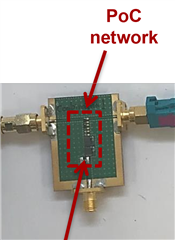
    Thank you. Is there a possibility that you will be able to share the layout used for this PCB:

    (taken from TI presentation Murata 97x PoC Inductor Solutions 2.pptx by TI)

    thanks a lot for your support.

    best regards,

    amotz

  • Hi Amotz,

    This board would have been provided by the coil vendor so I am not sure I would have the layout files to share.  Let me take a look but we may need to reach out to the vendor for additional guidance.

    Regards,

    Nick

  • Hi Amotz,

    This is probably a better question for Murata since this is not our board and I do not have the source files.  All I can share are the recommendations in the datasheet for the best performance however the vendor may have additional recommendations.

    Regards,

    Nick

  • Hi Nick,

    thanks, we are talking to their FAE.

    regards,

    amotz