This thread has been locked.

If you have a related question, please click the "Ask a related question" button in the top right corner. The newly created question will be automatically linked to this question.

SN65HVD72: About VP3082 Marking Code

Part Number: SN65HVD72
Other Parts Discussed in Thread: SN65HVD3082E

Hello,

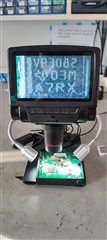
We are using SN65HVD72DR in our devices for RS-485 communication. But our EMS partner assembled another IC and the marking code is VP3082 as you can see at the attachment. I searched and found that VP3082 marking code is belong to SN65HVD3082ED. This product's voltage supply is 4.5V-5.5V but in our circuit we use 3.3V supply voltage for SN65HVD72DR so I think that this IC is not suitable for our product. Please give information about this.

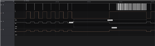
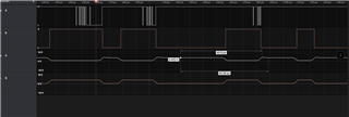
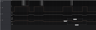
Another problem is we always test the products after our EMS partner manufacture the products. The tests were always succesfull so we didn't recognized that the IC is different from what we normally use. Is this even possible? I think that SN65HVD3082 IC shouldn't work with 3.3V supply.We need confirmation about this problem.

Best Regards.

  • Nihan,

    You are correct that VP3082 is the marking for SN65HVD3082ED and that this device only accepts 4.5V to 5.5V for a VCC supply. So if you're using 3.3V, it is peculiar that you're able to pass internal testing with applying 3.3V to VCC, since this won't fully power the IC. Can you explain a little bit about what testing you're doing to verify the manufacturing of your products? And is it possible to share waveforms of bus communication when you're applying 3.3V to the VCC pin of a device that has a top marking of VP3082?

    Regards,

    Eric Hackett 

  • Hello Eric,

    We use modbus poll and Yabe programs for modbus and Bacnet communication tests of our devices. While testing after connecting the device we set some parameters through the program so we can be sure the communication is okay. We test the device peer-to-peer. 

    You can see the attached waveforms of bus communication as digital and analog signals. 

  • Nihan,

    Are the bottom two waveforms the bus signals? I'm curious how they're reaching 4.337V if the supply is only 3.3V on the VCC pin. Is there another device on the bus that is set to 5V and pulling the voltage up?

    Regards,

    Eric Hackett 

  • Eric there is just Moxa Uport and Salaea logic analyzer on the bus. I checked the signal again thinking that we might measure wrong signals. You can see the bus signals at the attachment it is maximum 4V and I think that moxa might be the reason.

  • Nihan,

    Understood, just making sure that there indeed was a 3.3V signal on the VCC pin. I've notified our RS-485 expert to look at this further.

    Regards,

    Eric Hackett 

  • Nihan,

    SN65HVD3082E might still function with 3.3V supply. But many characteristics might not meet the specification in the datasheet. For example, the Vod could be smaller than 1.5V with 54Ohm load. However in applications, as long as the bus signal is larger than the receiver threshold (0.2V), the communication still work. 

    Regards,

  • Hello Hao L. Thank you for the reply. Would there be any problem when a lot of device is connected on the line? We want to connect 64 device but after connecting 36 devices we can't observe all devices on Yabe program. Like you said voltage level seems enough but communication is not good

  • Nihan,

    It's correct. As load is heavy, the driver is no longer able to provide enough current. Without connecting all the nodes, you can use resistor to mimic the lumped load impedance. For example, each node input impedance is about 96kOhm. With 30 node, the impedance becomes about 3.2kOhm. 

    Regards, 

  • I see.. Is there any way to boost the current in this situation? Actually we have a lot of devices in the field and we didn't know that our EMS partner has been using this IC for years. We recognized this situation now because one of our  customer connected a lot of device in the bus line but the communication didn't work. Would a RS-485 repeater work? We can not change the devices we need to find a solution to solve this problem

  • Nihan,

    Sorry for the delay here, but Hao is on vacation for the Thanksgiving holidays in the US this week. He will be back on Monday next week.

    Regards,

    Eric Hackett 

  • Nihan,

    If you cannot change the device or supply, is it possible to change the design? Do you have any termination resistors on bus? 

  • Hello Hao,

    We have activated the termination resistors at the beginning of the line and at the end of the line however it didn't work. If we communicate in slower rates such as 9.6kbps it is somehow working but most of our customers communicate in 76.8kbps so failure occurs in the line.

  • Nihan,

    I was suggesting that you remove the termination to get larger amplitude. As the termination are removed, you may also add pull up resistors on the A line and pull down resistors on the B line to further increase signal strength.