This thread has been locked.

If you have a related question, please click the "Ask a related question" button in the top right corner. The newly created question will be automatically linked to this question.

DP83869HM: The zynq7020 FMC board made by DP83869HM cannot be used

Part Number: DP83869HM
Other Parts Discussed in Thread: DP83869EVM, DP83869

Hi team,

I got a question from customer.I help him to post.

I used the DP83869HM chip to make the FMC board used in the zynq7020 development board as an external PHY chip. In the design, I refer to the schematic drawing in DP83869EVM, only change its power supply to FMC3.3V power supply, and the rest has not been greatly modified.


Question at this stage: The IO voltage I gave to DP83869HM is 3.3V, and the voltage of RX_D and TX_D measured is about 1.2V. However, after passing through the HX5008NL transformer, the voltage is almost unmeasurable, and the RJ45 network port cannot be used.


Consider the reasons: 1. After consulting, it was found that RJ45 was used for TS company production. The official description did not support Gigabit. Before communicating with TI technical staff, it indicated that it can support Gigabit. The specific situation is known, and it cannot be used at this stage~.

2. Zynq7020 uses a petalinux2019 system, considering that the DP83869 driver is not installed.

Question: 1. How to determine whether the DP83869 PHY chip is used and whether it works normally? (I found in the rebuilt petalinux2021.2 system.../tmp/.../drivers/net/phy/... that TI company provides most of the drivers for the PHY chip, including DP83867 and DP83869. Select it in petalinux-config -c kernel. After the operating system is generated, dp83869 still cannot be used, and the physical layer chip and Ethernet information cannot be recognized)

2. Or other issues that affect the application?

Thank you very much for your help.

Best regards,

  • Hello,

    Regarding item 1:

    I am not understanding the meaning of "FMC3.3V", "TS company production". Can you please expand on this? What do you mean that "The official description did not support Gigabit"? HX5008NL should support 1000Base-T.

    Regarding item 2:

    Just confirming that you got the Linux firmware from the correct location:

    https://www.ti.com/tool/ETHERNET-SW

    Sincerely,

    Gerome

  • Hello, Gerome
    I will attach my schematic diagram below.

    FMC_DP83869.pdf

    Could you please help me to check if there is any problem?
    "FMC3.3V" means that I made dp83869 as an FMC board and used zynq as the FMC backplane, and the power supply port used the 3.3V voltage provided by zynq. I don't know if the 3.3V voltage can complete the voltage supply.
    "Produced by TS company" refers to RJ45, I am not sure whether it can work normally, because the voltage is not enough to supply it.

    I found that there may be some problems with my strap configuration. I did not configure the straps of RX_0 and RX_1. I don't know if this is the reason that the board cannot be used?
    I have configured the rest of the straps, but when LED[0]--LED[2] is connected to "0", its corresponding three lights, LD5, LD3, and LD1, do not light up.

    Thank you for your answer, thank you!

  • Hello,

    Thank you for clarifying and uploading the schematic. Typically, schematic reviews take a 5 working day turnaround, but especially as next week is Thanksgiving in US, I will try to get feedback to you by end of day Wednesday at the latest. I may ask followup questions between then.

    Sincerely,

    Gerome

  • Hi Gerome,

    Is there any update?

    Thank you!

    Best regards,

  • Hi Zhonghui,

    My feedback from schematic:

    - Please adjust power supply decoupling capacitors to be more like the configuration in datasheet

    - Ensure that you are supplying 1.1V to pins 6, 31, 39

    - Ensure when using SMI that there is a 2.21k pullup resistor to VDDIO on that node

    - For C61, 62, 64, 66, 67, 69, 70, 72; it appears you are AC shorting across the magnetics. What is the purpose of this?

    You could also probe the supplies at the pins to see if the proper voltages are getting to the PHY. If you are concerned about supply not being able to support entire system, you can see if there is any unintended voltage at those power pins.

    Sincerely,

    Gerome

    Note: The US office will be closed 11/25 and 11/26 for thanksgiving holiday. Please expect delayed responses. We will be open on 11/29.

  • Hi Gerome,
    I successfully applied for an account in the English forum and can now post a reply.
    For your feedback, I made a measurement, I will attach the voltage value of each pin in the table below, please help me to check it.DP83869.xls
    To reiterate, my schematic is derived from the schematic of DP83869EVM, so many settings may not be particularly familiar to me.
    Regarding your feedback:
    1. I used a voltage of 1.0V instead of a voltage of 1.1V, don't you know that it will have an impact?
    2. When using SMI, I did miss the 2.21K pull-up resistor to VDDIO.
    3. For C61, 62, 64, 66, 67, 69, 70, 72; I also don't understand its role in AC short circuit, it comes from the official schematic diagram.

    4、In the schematic, I also missed the configuration pins about RX_D0 and RX_D1.
    Thank you!
    Best regards,

  • Hello,

    For C61, 62, 64, 66, 67, 69, 70, 72; These are DNP'ed in the EVM schematic. Are they also DNP'ed in your design?

    Regarding the 1.1V rail, having a 1.0V supply on it does work, but it is on the lower side. Please see section 8.3 of datasheet where Recommended Operating Conditions for the pin are 0.99V to 1.21V. If the LDO you are using were to dip by 10mV off the nominal, then we cannot guarantee performance of the device as the rail might not be sufficiently powered.

    Regarding strapping of RX_D0 and RX_D1, if the intended address for the PHY is 0x0, then having no PU or PD resistor is sufficient due to the internal PD of the device. If this is the case, please ensure there is no resistor to supply nor GND on the MAC side either.

    Sincerely,

    Gerome

  • Hi Gerome,
    I did ignore the DNP processing on the EVM board, but after I tried to solder off all the DNP-processed devices, my board still couldn't be used and could not recognize the Ethernet. Is there any test method to observe whether my physical layer chip is working properly?

    Thank you!
    Best regards,

  • Hello,

    You can try using register 0x9[15:13] to enable different test modes. These are fixed waveforms. I would also probe before and after the magnetics to see where the signal is getting lost. You reported this behavior prior when the DNP'ed components were still on board. Is this behavior still present?

    Also, please probe the power pins to ensure supply is adequate.

    Taking a step back, are you able to access using SMI? Can you describe more about how you PHY is not working properly? Is it getting not getting link when connecting to a LP? Are you doing testing?

    Sincerely,

    Gerome

  • Hi Gerome,
    I'm sorry that I haven't responded in the past few days. I have conducted some tests in the past few days. The details of the tests are as follows.
    About the debugging status of DP83869 FMC board

    1. The board card use environment: zynq7020+petalinux system, use FMC interface to connect DP83869 chip, transmit RGMII signal, MDIO/MDC signal and 3.3V voltage supply.

    2. Driver debugging: add dp83869 driver in petalinux system
    In the module of petalinux2019.1, add a custom driver, and the build is successful, but the network port does not respond
    In petalinux2021.1, use petalinux-config -c kernel to select the DP83869 driver in the kernel, and the build is successful, but the network port does not respond

    3. Hardware test: use oscilloscope and multimeter to test.
    Power supply: 3.3V IO power supply, 2.5V, 1.0V power supply are no problem
    Clock crystal oscillator: local oscillator is adopted, and both XI/XO ports are 25MHZ. (The XI/XO connection in the schematic diagram here is reversed, I don't know what the impact will be)

    The following table shows the clock values of GTX_CLK and RX_CLK when configuring the LED strap.


    GTX_CLK/MHz

    RX_CLK/MHz

    000

    125

    2.5

    001

    125

    2.5

    010

    125

    2.5

    011

    125

    2.5

    100

    125

    125

    101

    125

    2.5

    110

    125

    125

    111     125                      2.5


    Strap configuration: PHY_ADDR is configured as 0x0; when the LED is configured as 000, the measured RX_CLK clock is automatically negotiated as 2.5MHz

    MDC/MDIO: It can be measured by an oscilloscope. There are always 6 register configurations, namely:
    1. 0110 00000 00001 z0 0111 1001 0100 1001 The auto-negotiation process is not completed; no jabber is detected; the link is disconnected
    2. 0110 00000 01010 z0 0111 1001 0100 1001
    3. 0110 00000 01010 z0 0000 0000 0000 0000 The local PHY configuration is resolved as a slave; the local receiver is abnormal; the remote receiver is abnormal
    4. 0110 00000 01001 z0 0001 0010 0000 0000 start manual master/slave configuration; announce 1000Baes-T full duplex capability
    5. 0110 00000 00101 z0 0000 0000 0000 0000
    6. 0110 00000 00100 z0 0000 0001 1110 0001 Non-straps default to "1"; 802.3

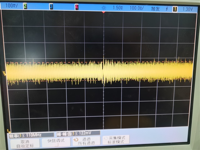
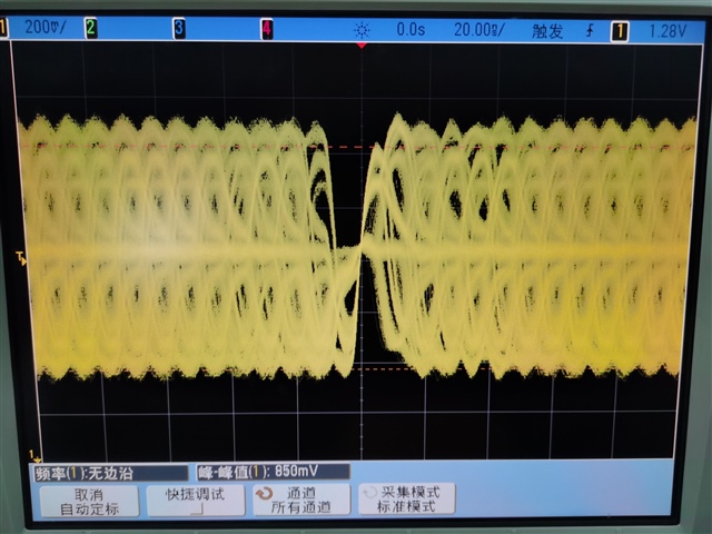
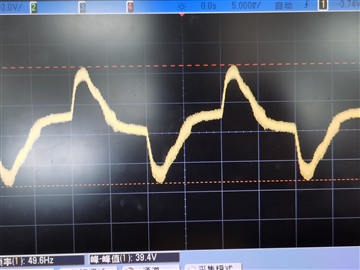
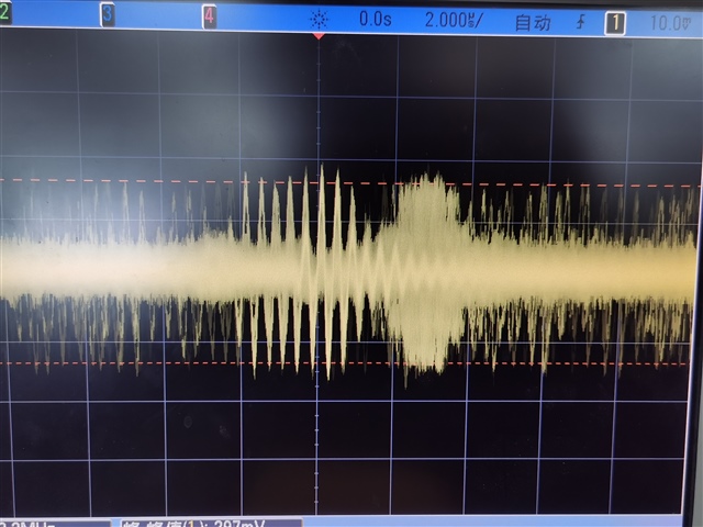
    4. When I use EARTH_GND to measure the differential data signal. In the front part of the transformer, I get a stable waveform of 50HZ; while at the back end of the transformer, I can only get a waveform similar to noise, as shown in Figure 1-2 below. When using GND for measurement, they are all similar to noise waveforms, as shown in Figure 3-4 below.

    I wonder if you can derive the reason or clue that its Ethernet is not recognized from this information?

    Thank you!
    Best regards,

  • Hello,

    I am trying to understand the issue at hand. Can you confirm that the behavior you are seeing is PHY is not linking with LP when connecting via RJ-45? Is there any other issues you are seeing on your side that prevent functionality?

    Can you also confirm the voltage at 1P1 power pin?

    It seems like you are having driver issues with your custom driver. If you try swapping using our Linux driver for DP83869HM located at https://www.ti.com/tool/ETHERNET-SW, does this solution work?

    While scoping is helpful, are you able to read registers in SW or via our USB2MDIO GUI? Would like to see a register dump if possible to best get details of what is going on configuration-wise inside PHY.

    Sincerely,

    Gerome

  • Hi Gerome,
    The driver I used is the official driver provided by TI, and he can't work either.
    I'm sorry I didn't understand what LP means. If it refers to my PC, after connecting the Internet cable, the Ethernet port option does not appear on my computer. This is the problem I am encountering now.
    I determined the voltage on VDDA1P1, which is 0.9984V.
    I tried to use the USB-MDIO software, but the information I can get is: Register is: Error! Device not connected!

    Thank you very much for your help.

    Best regards,
  • Hello,

    By LP I do mean link partner, so yes, your PC if this is on the other side of the cable would be the case.

    I would advise using a different voltage source on VDDA1P1 as this is getting really close to the lower end of RoC.

    When it comes to using USB2MDIO, what is your setup for this? Are you using a launchpad? Is it flashed with the appropriate firmware for USB2MDIO compatibility? What pins of the Launchpad are being connected to what pins of the PHY?

    Sincerely,

    Gerome

  • Hi Gerome,
    Sorry, but I did not use MSP430 as my processor. Is this the reason why the software cannot be used? I use the MDIO interface on the PS side in zynq to connect to the SMI in the PHY. I tried to use the uart port to connect to my PC to run the software, but I failed.

    Thank you very much for your help.

    Best regards,
  • Hello,

    Yes, USB2MDIO expects a MSP launchpad as the device to interface with PHY. 

    Sincerely,

    Gerome