This thread has been locked.

If you have a related question, please click the "Ask a related question" button in the top right corner. The newly created question will be automatically linked to this question.

SN65DSI86: SDP Pattern

Part Number: SN65DSI86


I would like to ask some problems about how to send SDP pattern by SN65DSI86...

I want send a SDP packet with Header = HB0, HB1, HB2, HB3 and Data = DB0 DB1 DB2 DB3 DB4 DB5 DB6 DB7

According to spec, I should embed this SDP data in Vertical Blanking Time.

so, I build a MIPI Generic Write Packet in VBP first line with follwing data:

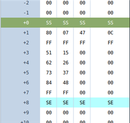
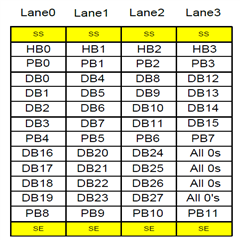
0x29 0x12 0x00 ECC 0x00 0x80 HB0 HB1 HB2 HB3 PB0 PB1 PB2 PB3 DB0 DB1 DB2 DB3 DB4 DB5 DB6 DB7 PB4 PB5 CRC_L CRC_H

However, it does not work.

Can you provide some suggestion or more detailed cotrol flow about SDP? 

And hould I build SDP pattern in Left Port or Right Port or Both if my DSI environment is 2 port?


Thank you very much

  • update byte sequence which I really sent:

    0x29 0x1E 0x00 0x20 0x00 0x80 0x00 0x87 0x00 0x4C 0xFF 0xFF 0xFF 0xFF 0x55 0xAA 0x66 0x99 0x55 0xAA 0x66 0x99 0xFF 0xFF 0x55 0xAA 0x66 0x99 0x00 0x00 0x00 0x00 0xFF 0xFF 0x5F 0x06


    which DataType = 0x29,

    WC=0x001E,

    ECC=0x20,

    Header = 0x00 0x87 0x00 0x4C,

    Payload = 0x55 0xAA 0x66 0x99 0x55 0xAA 0x66 0x99 0x55 0xAA 0x66 0x99 0x00 0x00 0x00 0x00

    CRC = 0x065F

  • Hi,

    For the secondary data packet, these are transmitted over the DP interface during the vertical blanking period. The SN65DSI86 requires that the SDP be provided to the DSI interface in the following order:

    1. 4 Bytes of Header (HB0 through HB3)

    2. 4 Bytes of Header parity (PB0 through PB3)

    3. 8 Bytes of Data (DB0 through DB7)

    4. 2 Bytes of Data parity (PB4 and PB5)

    5. 8 Bytes of Data (DB8 through DB15)

    6. 2 Bytes of Data parity (PB6 and PB7)

    Thanks

    David

  • which you mentioned is listed at SN65DSI86 spec, and I followed this rule to send DSI packet (shown as previous post). But I can not get info at RX SDP receiever log.

    so ...

    1. Is there any suggestion or more detailed control flow?

    2. How should I embed DSI packet at DSI 2 port environment? Left Port? Right Port? Both Port?

  • Hi,

    Since SDP is sent from the DSI86, across the AUX to the eDP sink? Have you checked and verified the AUX is working properly?

    Can you use this SW example code to read the eDP EDID?

    This script will read 256 bytes of the EDID.
    <aardvark>
    <configure i2c="1" spi="1" gpio="0" tpower="1" pullups="0" />
    <i2c_bitrate khz="100" />
    ======Enable I2C_ADDR_CLAIM1======
    <i2c_write addr="0x2D" count="1" radix="16">60 A1</i2c_write> />
    ======Write EDID base of 00 ======
    <i2c_write addr="0x50" count="0" radix="16">00</i2c_write> />
    ======Read 256 bytes of EEID======
    <i2c_read addr="0x50" count="256" radix="16">00</i2c_read> />
    </aardvark>

    Thanks

    David 

  • From my understanding of DP and DSI86 spec, SDP will be sent by eDP mainlink instead of AUX.

    I have checked AUX worked well and I can light-on eDP panel correctly, but get troubled when using SDP.

    I embedded a Generic write packet as preivous post in DSI stream VBP area and expected RX can get SDP data. However, it doesn't work.

    So... Is there any application note about DSI86 SDP?

  • Hi, 

    You are right that the SDP is transmitted across the main link, this is a mistake on my part. 

    If you change the ADDR to 0x00, then the SN65DSI86 will interpret the Generic Long Write to target its CFR space. In this case, are you able to read and write the DSI86 registers? 

    If reading/writing to the DSI86 registers is working, do you have a way to decode the data on the eDP main link? I want to see if the SDP is actually being transmitted or not.

    Thanks

    David

  • Hi David,

    I have tried replace SDP packet with CFR write packet. and I can see CFR write result after send DSI video stream.
    CFR write only works at WC=3 (ADDR_L, ADDR_H, WrData), and I found it's mentioned at note of spec section 8.4.4.3.3.
    it proves that my DSI pattern generation engine works well.

    so... Let's return to the subject.
    I embed a MIPI Generic Write, which is composed of 0x29, 0x14, 0x00, 0x19, 0x00, 0x80, 0x00, 0x87, 0x00, 0x4C, 0xFF, 0xFF, 0xFF, 0xFF, 0x12, 0x34, 0x56, 0x78, 0x00, 0x00, 0x00, 0x00, 0xFF, 0xFF, 0x88, 0x58 into VBP first line of my DSI video stream.
    And, I expect my RX can receive a SDP data which header=0x00, 0x87, 0x00, 0x4c and Data=0x12, 0x34, 0x56, 0x78.

    sorry for information lost... my RX only can identify specified header, that is 0x00, 0x87, 0xXX, 0x4C, and ignore any other SDP data with other header.
    I don't have a valid method to decode eDP mainlink yet.
    so ... I have no way to distinguish whether DSI86 sends SDP data with unexpected header or DSI86 did not send SDP data.

  • Hi,

    Are you trying to send CEA-861-F Non-audio INFOFRAME packet? 

    For INFOFRAME SDP v1.2, HBR2 must be 0x1Bh and HBR3 must be 0x12h.

    Thanks

    David

  • Hey... It has been many times...

    Can you focus on how to send SDP packet by SN65DSI86 please?

    This function is mentioned at DSI86 spec, so I believe that SDP function is fully supported or partial supported.

    Can you provide some detailed information, ex.

    Where should SDP packet be inserted at DSI stream, VBP? VFP? Or other position?

    Should I keep the line time, which SDP packet is inserted, equal as normal horizontal blanking line?

  • Hi,

    The SDP needs to be sent during vertical blanking period, VBP or VFP. I am not clear on your second question "equal as normal horizontal blanking line".

    You need to make sure the data packet format and parity are correct. It looks like the header packet you are sending is not following the DP spec. The DSI86 will just pass through the SDP packet, but the sink may reject the SDP if the header, data packet format and parity are not correct.

    Thanks

    David

  • Assume normal line time of DSI stream is x, and time which SDP packet takes is y.
    The line which SDP is inserted line should be x + y or just x?

    So ...
    "The DSI86 will just pass through the SDP packet althrough parity or header format is invalid."
    Right?

  • Hi,

    Assume normal line time of DSI stream is x, and time which SDP packet takes is y.
    The line which SDP is inserted line should be x + y or just x?

    Just X

    "The DSI86 will just pass through the SDP packet althrough parity or header format is invalid."
    Right?

    Correct, the DSI86 does not check the parity, the header format, or the CRC of the SDP packet.

    Thanks

    David

  • Hi,

    Finally, I get a instrument to decode eDP mainlink and check SDP exists or not.
    As the following png file, I get expected decoded result because DSI86 is sending H-gradient pattern.

    Regard of SDP data, I get decoded result unexpected.
    SDP payload is 0x11,0x22,0x33,0x44,0x55,0x66,0x77,0x88,
    So the DSI packet I embedded is 0x29,0x14,0x00,0x19,0x00,0x80,0x00,0x87,0x07,0x4C,0xFF,0xFF,0xFF,0xFF,0x11,0x22,0x33,0x44,0x55,0x66,0x77,0x88,0xFF,0xFF,0x1E,0xEF
    as the following png file, it is seemded my SDP header and payload is split by some rule.

    So ...
    1. Is there some document or spec I lost about SDP payload?
    2. Should I follow some rule to build SDP payload to DSI packet? If yes, what is the rules?

  • Hi,

    Do you have a copy of the DisplayPort spec? I would refer to section 2.2.5 of the spec for the SDP format. The SDP packet format across the main link is different depending on the packet type. For example, below is the InfoFrame packet format.


    Do you clear the 0xF0 to 0xF8 status registers before sending the SDP?  If not, please do so.  Clear by writing 0xFF to these registers. After you sending the SDP packet, you can then read the status registers to see if DSI error is being reported. I want to make sure there is no timing or signal integrity issue being associated with the DSI interface.

    Thanks
    David 

  • Hi David,

    I cannot check DSI error report...
    I found 0xF0 register is 0x02 and 0xF6 register is 0x40 when DSI86 is sending normal video stream,
    and 0xF0 register is 0x02, 0xF1 register is 0x2D, 0xF6 register is 0x40 when DSI86 is sending video stream with SDP packet.

    bit 1 of register 0xF0 is CHA_SOT_SYNC_ERR.
    bit 5 of register 0xF1 is CHA_INVALID_LENGTH_ERR.
    bit 3 of register 0xF1 is CHA_DATATYPE_ERR.
    bit 2 of register 0xF1 is CHA_CHECKSUM_ERR
    bit 0 of register 0xF1 is CHA_COR_ECC_ERR.
    bit 6 of register 0xF6 is LOSS_OF_DP_SYNC_LOCK_ERR.

    so...
    1. About SOT Sync Error, Is DSI86 DSI AC Timing specification is listed on spec?
    That is, what is the the following timing parameters exact value and unit of DSI86?
    TclkPrepare, TclkZero, TclkPre, TclkPost, TclkTrail, ThsPrepare, ThsZero, ThsTrail, ThsExist
    for example, TclkPrepare needs to be 3 UI typically, or TclkZero needs to be 100 ns typically.

    2. About CHA_DATATYPE_ERR, when DSI is sending DSI stream with SDP packet, I replacement some blanking time to SDP packet.
    and DSI packet data type of SDP is 0x29. I don't know why CHA_DATATYPE_ERR occured.

    3. About Others, I will re-check my composition of DSI stream.

  • Hi,

    Did you clear the status register before you read them? I want to make sure the reported error are real. If the errors are real, then you need to check the setup and hold timing on the DSI interface as defined below.

    Thanks

    David

  • Hi,

    According to snapshot of previous post, I found a rule about DSI packet and SDP payload.

    Finally, I re-arrange my payload and get the desired decoded result.
    Thanks!