This thread has been locked.

If you have a related question, please click the "Ask a related question" button in the top right corner. The newly created question will be automatically linked to this question.

DP83TC811R-Q1: Driver code guide

Part Number: DP83TC811R-Q1
Other Parts Discussed in Thread: TDA2HG

Hi Experts,

Our customer using DP83TC811R-T1 on their module, the driver code is download from our website, because of 811s and 811R share the same code, customer software engineers want to have a user guide to know how to change the base line code to meet their specific applications? do we have such of those user guide file? 

currently when they read the indirect register of  811R(not change the base line code), the value is incorrect ...

  • Hello Andy Ye, 

    Thank you for the query.

    If i understand correctly, you are looking for user guide for the driver that customer has downloaded. I am not aware of any guide but based on your confirmation, i can check internally.

    Regarding the external register access, the procedure is different from reading the basic register. Is customer able to read the basic registers ?

    Regards,

    Sreenivasa

  • Hi Kallikuppa,

    Yes , currently customer can be read/write basic registers(0x0~0x1F) correctly, but for M

     reg:[0], value:[0x2100]
     reg:[1], value:[0x65]
     reg:[0], value:[0x2100]
     reg:[1], value:[0x65]
     reg:[2], value:[0x2000]
     reg:[3], value:[0xa253]
     reg:[9], value:[0x2000]
     reg:[d], value:[0x401f]
     reg:[e], value:[0xa1]
     reg:[11], value:[0x10b]
     reg:[12], value:[0x6400]
     reg:[13], value:[0x4200]
     reg:[14], value:[0x0]
     reg:[15], value:[0x0]
     reg:[16], value:[0x100]
     reg:[17], value:[0x524d]
     reg:[18], value:[0x1810]
     reg:[1b], value:[0x7d]
     reg:[1c], value:[0x5ee]
     reg:[1e], value:[0x0]
     reg:[1f], value:[0x0]
     reg:[133], value:[0xffea]
     reg:[16b], value:[0xffea]
     reg:[180], value:[0xffea]
     reg:[18a], value:[0xffea]
     reg:[18b], value:[0xffea]
     reg:[18c], value:[0xffea]
     reg:[198], value:[0xffea]
     reg:[400], value:[0xffea]
     reg:[401], value:[0xffea]
     reg:[446], value:[0xffea]
     reg:[448], value:[0xffea]
     reg:[460], value:[0xffea]
     reg:[461], value:[0xffea]
     reg:[462], value:[0xffea]
     reg:[463], value:[0xffea]
     reg:[467], value:[0xffea]
     reg:[469], value:[0xffea]
     reg:[475], value:[0xffea]
     reg:[480], value:[0xffea]
     reg:[482], value:[0xffea]
     reg:[483], value:[0xffea]
     reg:[485], value:[0xffea]
     reg:[486], value:[0xffea]
     reg:[487], value:[0xffea]
     reg:[489], value:[0xffea]
     reg:[496], value:[0xffea]
     reg:[4a0], value:[0xffea]
     reg:[4a1], value:[0xffea]
     reg:[4a2], value:[0xffea]
     reg:[4a3], value:[0xffea]
     reg:[4a4], value:[0xffea]
     reg:[4a5], value:[0xffea]
     reg:[4a6], value:[0xffea]
     reg:[4a7], value:[0xffea]
     reg:[4a8], value:[0xffea]
     reg:[4a9], value:[0xffea]
     reg:[4aa], value:[0xffea]
     reg:[4ab], value:[0xffea]
     reg:[4ac], value:[0xffea]
     reg:[4ad], value:[0xffea]
     reg:[4ae], value:[0xffea]
     reg:[4af], value:[0xffea]
     reg:[4b0], value:[0xffea]
     reg:[4b1], value:[0xffea]
     reg:[4b2], value:[0xffea]
     reg:[4b3], value:[0xffea]
     reg:[4b4], value:[0xffea]
     reg:[4b5], value:[0xffea]
     reg:[4b6], value:[0xffea]
     reg:[4b7], value:[0xffea]
     reg:[4b8], value:[0xffea]
     reg:[4b9], value:[0xffea]
     reg:[4ba], value:[0xffea]
     reg:[4bb], value:[0xffea]
     reg:[4bc], value:[0xffea]
     reg:[4bd], value:[0xffea]
     reg:[4be], value:[0xffea]
     reg:[4bf], value:[0xffea]
     reg:[4c0], value:[0xffea]
     reg:[4c1], value:[0xffea]
     reg:[4c2], value:[0xffea]
     reg:[4c3], value:[0xffea]
     reg:[4c4], value:[0xffea]
     reg:[4c5], value:[0xffea]
     reg:[4c7], value:[0xffea]
     reg:[4c8], value:[0xffea]
     reg:[4c9], value:[0xffea]
     reg:[4ca], value:[0xffea]
     reg:[4cb], value:[0xffea]
     reg:[4cc], value:[0xffea]
     reg:[4e0], value:[0xffea]
     reg:[4e5], value:[0xffea]
     reg:[7], value:[0x2001]
     reg:[b], value:[0x1000]
     reg:[12], value:[0x0]
     reg:[834], value:[0xffea]
     reg:[836], value:[0xffea]
    4e0], value:[0xffea]
    
     reg:[4e5], value:[0xffea]
    
     reg:[7], value:[0x2001]
    
     reg:[b], value:[0x1000]
    
     reg:[12], value:[0x0]
    
     reg:[834], value:[0xffea]
    
     reg:[836], value:[0xffea]
    
    
    MD1F field register they access is incorrect(attached), I find they are not change the baseline driver code and not follow our spec  section 8.6.1 register access method .

    Now customer should change the baseline code, so they asked do we have a user guide of how to change the baseline driver code, they were afraid of make mistakes.

  • Hello Andy Ye, 

    Thank you for the message. Can you please ask customer to use the extended register access for registers above 1F. I am checking internally.

    Regards,

    Sreenivasa

  • Hello Kallikuppa,

    Now, customer change the code , and can be access all registers. PHY to PHY already link up (0x0133 = 0x75FF),PHY to MAC(TDA2HG) also link seems ok(0x0001 = 0x0065), but from MAC side view, RGMII port working at 10Mbps half-duplex not 100Mbps full-duplex, we test RX_CLK and TX_CLK signal, the frequency is 25MHZ, I don't know whether is our PHY issue or SOC issue?

    I find the datasheet about in-band mode, could you tell me what is in-band mode ?this issue is caused by this ?

  • Hello Andy Ye, 

    The table is status indication and not mode. What is customer reading ?

    Can you please check the basis for customer to conclude the device is operating in 10M mode ?

    What interface is customer using ?

    Regards,

    Sreenivasa

  • Hi Kallikuppa,

    The interface is RGMII, the basis for customer to conclude the device is operating in 10M is from MAC(TDA2HG) side view

    from our PHY side, registers value seems no issue, 0x0000 =0x2100(Bit 8 =1 means full duplex ? ); 0x0001 = 0x0065; 0x0133 = 0x75ff, 0x0467 = 0x00fc;

    Updated this morning checking results:

    MAC side configured RGMII port as auto-negotiation  , but I see from our datasheet, 811R RGMII can't support auto-negotiation, so MAC(TDA2HG) switch to 10M half duplex .

  • Hello Andy Ye, 

    Thank you for the reply.

    Updated this morning checking results:

    Sorry i cant understand this.

    MAC side configured RGMII port as auto-negotiation  , but I see from our datasheet, 811R RGMII can't support auto-negotiation, so MAC(TDA2HG) switch to 10M half duplex .

    Did you mean auto negotiation for the RGMII interface ?

    Regards,

    Sreenivasa

  • Hi Kallikuppa,

    Yes, auto negotiation for the RGMII interface, MAC side configured. 

  • Hello Andy Ye, 

    Thank you for the message. 

    Can you help me understand the support required for the applications side.

    Regards,

    Seenivasa

  • Hi Kallikuppa,

    Thanks for your support.

    Two items I want you confirm, 

    1. Does DP83TC811R RGMII port support auto-negotiation or not ?

    2. From  DP83TC811R side, how to know whether RGMII port working as half-duplex or full-duplex mode, is there any registers to configure or show about this ?

  • Hello Andy Ye, 

    Thank you for the reply.

    I will review the questions and update you.

    Regards,

    Sreenivasa

  • Hello Kallikuppa,

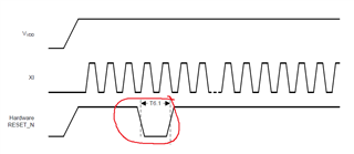
    Currently customer reset sequence is not totally follow our spec,

    asserting this pin LOW for at least 1 μs again .

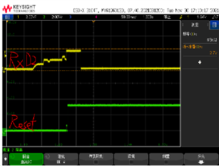
    customer board reset signal wave form as following:

    my question is whether it affect normal operation if not assert reset_n pin as low more 1us again when power up? because currently customer circuit can't change.

    and I also have little confused about our link status register:

    1) 0x0001 bit2 link status --- It means MAC to PHY link  or  PHY to PHY 100BASE-T1 link status ?

    2) 0x0133 bit12 link status --- It means MAC to PHY link or PHY to PHY 100BASE-T1 link status ?

    0x0133 bit1/0 link status --- It means MAC to PHY link or PHY to PHY 100BASE-T1 link status ?

  • Hello Andy Ye, 

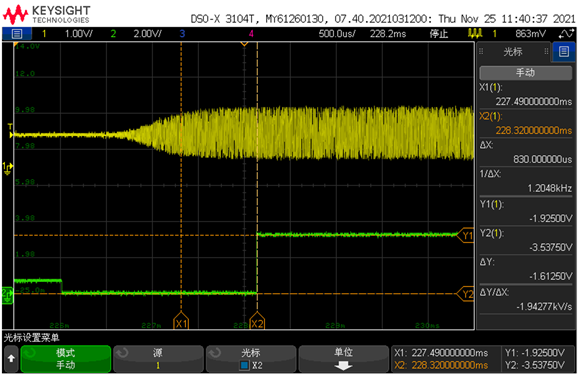
    Please capture the reset with respect to clock and  power supply.

    Regards,

    Sreenivasa

  • Hi Kallikuppa,

    Following is reset  vs clock wave form:

  • Hello Andy Ye, 

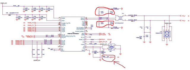
    I do not have the schematics to  review and comment.

    Can you please provide the time in ms between the VDD being stable and reset going high ?

    See below reset function definition

    All digital circuitry is cleared along with register settings during reset. Once reset completes, device bootstraps are resampled
    and associated bootstrap registers are set accordingly.

    Regards,

    Sreenivaa

  • Hi Kallikuppa,

    Following is customer schematic, I already point out 2 of errors, customer changed, the VDD being stable and reset going high interval is about 3ms,

    currently customer can be read correct bootstraps value(0X0467 = 0xfc).

    can you pls help me to confirm link status registers indications? 

    link status register:

    1) 0x0001 bit2 link status --- It means MAC to PHY link  or  PHY to PHY 100BASE-T1 link status ?

    2) 0x0133 bit12 link status --- It means MAC to PHY link or PHY to PHY 100BASE-T1 link status ?

    0x0133 bit1/0 link status --- It means MAC to PHY link or PHY to PHY 100BASE-T1 link status ?

    thanks !

  • Hello Andy Ye, 

    Thank you for the inputs.

    The registers that you have listed are for the MDI interface.

    Regards,

    Sreenivasa

  • Hello Andy Ye, 

    Thank you for the schematics. I am having trouble seeing the picture clearly. I see the reset being connected to some net. Is this connected to some fixed reset or host interface ?

    Regards,

    Sreenivasa

  • Hello Kallikuppa,

    Reset pin connect to host interface of SOC, this pin also connect to other IC reset, so customer told me this circuit can't change the reset sequence.

  • Hello Andy Ye, 

    Thank you for the reply.

    Is the reset controlled by the Reset IC or the host ?

    Regards,

    Sreenivasa

  • Hello Andy Ye, 

    This is the input i received 

    As 811 is only a single speed device (100Mbps), we don’t support/need auto-negotiation. MAC side should be able to read the advertised support and switch to fix 100Mbps mode when  required.

    Regards,

    Sreenivasa

  • Hi Kallikuppa,

    Currently circuit PHY reset controlled by reset IC.

  • Hello Andy Ye, 

    Thank you for the inputs.

    Please note that the clock should be stable before the reset goes high. 

    The oscillator startup  depends on the device, layout and other components used.

    Regards,

    Sreenivasa

  • Hello Andy Ye, 

    Please note that the clock should be stable before the reset goes high. 

    The oscillator startup  depends on the device, layout and other components used.

    There is no timing requirement for the Reset to go high after the power supply and the clock is stabilized.

    Regards,

    Sreenivasa 

  • Hello Andy Ye, 

    Please let me know if you have additional questions.

    Regards,

    Sreenivasa

  • Hello Kallikuppa,

    No additional questions, thanks for your support !

  • Hello Andy Ye, 

    Thank you for the reply.

    Could you please click the resolved button to close the thread.

    Regards,

    Sreenivasa

  • Hello Andy Ye, 

    I am closing the thread from my side.

    Regards,

    Sreenivasa