This thread has been locked.

If you have a related question, please click the "Ask a related question" button in the top right corner. The newly created question will be automatically linked to this question.

DS90UB954-Q1: If only RIN0 is used but not RIN1, can RIN1 be floating?

Part Number: DS90UB954-Q1

Hi Team,

There have one thing need your support!

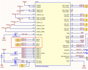
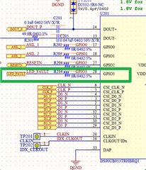
RIN0 & RIN1 are two sets of TX inputs. If the customer only uses RIN0, is it recommended to floating RIN1? If only RIN0 is used but not RIN1, can RIN1 be floating?
Because this 954 adapter board will be used in the customer’s camera module in the future, and the RX terminal will be illuminated when testing EMC, it is necessary to consider the lowest EMI,
, So I want to confirm with your suggestion? THX

  • Hello Kygo,

    You can leave them floating and disable them per register, or you can terminate them to GND via CAPs and 50 ohm resistors.

    Best Regards,

    Shruti

  • Hi Shruti,

    After discuss with customer,

    One thing need to check with you,

    The GPIO of 953 can read the status of GPIO through I2C whether it is high or low?


    Customer application is that the error pin of the image sensor or LED driver will be connected to the 953's GPIO. When an error occurs on the sensor, and  the sensor error pin will be pulled down. At this time, the IO status is reported to the ECU host through I2C. Is this OK?

  • Hello Kygo,

    Yes, GPIO0 through GPIO3 can be monitored, configured, and controlled through the I2C bus in registers 0x0D, 0x0E, and 0x53. 

    Yes, it is okay to implement what you described, but keep in mind that the GPIO3 status will be known when you read reg 0x53. When the error pin of the image sensor or LED driver changes status, GPIO3 will not automatically flag the change in status or notify via any other register. You will have to read reg 0x53 each time you want to know the status of the GPIO3 pin. 

    Best Regards,

    Shruti