Part Number: TUSB9261
Good morning,
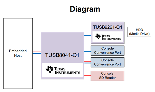
I'm working on a new design. My block diagram is very similar to the block diagram in the data sheet -below. However, I'm using two TUSB9261 devices. The host is a Windows 10 PC.
The HDD is a 1TB Samsung SSD 850 EVO.
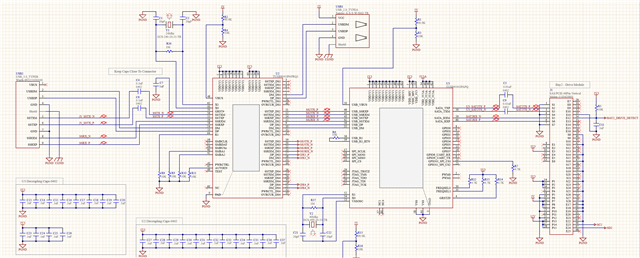
The end-to-end schematic is below detailing the USB->TUSB8041->TUSB9261->SDD Connector. There is no polarity swap on differential lines.
The 8041 and both 9261's enumerate properly.
I purchased the TUSB9261DEMO Eval Kit. At the very end of this note is how this kit is enumerating. I can plug the SDD into this slot and it works.
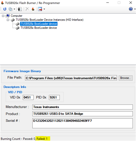
I would like to program my two 9261's to the same as the demo 9261 device.
ISSUE:
When I attempt to program my device(s) it fails. See below. I've tried it several times and it always fails.
Please help with any suggestions.
Thank you,
-Tony
BLOCK DIAGRAM:
SCHEMATIC:
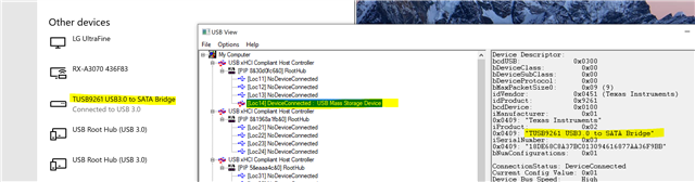
USB ENUMERATION:

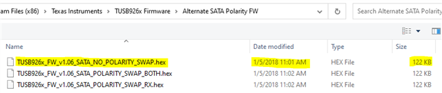
FLASH PROGRAM HEX FILE:
PROGRAMMER FAIL:
HOW THE DEMO-EVAL KIT ENUMERATES: