Because of the Thanksgiving holiday in the U.S., TI E2E™ design support forum responses may be delayed from November 25 through December 2. Thank you for your patience.

This thread has been locked.

If you have a related question, please click the "Ask a related question" button in the top right corner. The newly created question will be automatically linked to this question.

PCF8575: Using PCF8575 pins as input

Part Number: PCF8575
Other Parts Discussed in Thread: SN74HC14

Hi TI Technical Support Team,

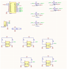
I have designed a PCB to read 5 TCRT5000 sensor outputs. I connected TCRT5000 outputs to 74HC14D schmitt trigger, and using PCF8575 pins, I am reading outputs of schmitt trigger (Either high or low). Previously, I have used PCF8575 to expand my mcu output pins. For this board my aim is to increase number of input pins of my mcu. My mcu board and pcb board with PCF8575 are two separate boards and I am connecting them with cable (3.3V, GND, SCL, SDA).

When I just power the board with 3.3V and GND (and donot connect MCU SCL SDA pins), and check the inputs of PCF8575 inputs (or output of 74hc14d) it is behaving as expected (when sensor see black or white surface the PCF8575 inputs are HIGH or LOW as expected). However, when I connect the SCL SDA to the board and upload code to MCU (I am defining PCF8575 pins as input), and check the inputs of PCF8575 (using software or multimeter), it is always low (I cannot see HIGH on pins of PCF8575, whatever surface the sensor sees).  I have attached the board schematic to this question.

I have read the datasheet of PCF8575 and some questions answered in this forum regarding to this IC. I think the problem is related to defining the pins of PCF8575 as input in my code.

Do you think using some 10k pullup resistor to 3.3V on PCF8575 input pins will solve the problem? Can I solve the issue through code? 

Thank you in advance for your help,

Ahmet
  • To allow the pins to work as inputs, you must output a high level (which is the default).

    How does your code initialize the pins? What is the voltage you measure at the pins with your code?

  • Ahmet,

    Thanks for the information and for reaching out. As Clemens correctly noted, it seems possible that during initialization, the pins are being initialized as LOW rather than HIGH. This would explain why the pins of the PCF8575 fall low after startup. The PCF8575 pulls down strongly, which is why it could be overcoming the signals that would otherwise be HIGH from the SN74HC14 devices. When configured as HIGH, it is weaker, and it should allow both high and low signals to manifest at the P-ports.

    Best,

    Danny

  • Hi, 

    Thanks Clemens and Dany for the help.

    Actually, I donot initialize them during startup, I mean I directly define the pins of PCF8575 as input then I begin to read the inputs. When the SN74HC14 output is LOW, there is no problem, but when I expect the output to be HIGH, I measure them as LOW again (0.369 V with multimeter). I tried with 10k pull up resistor, but the result is again same. 

    As you suggested, I will output HIGH from my code before initializing and defining pins as input and making input read. 

    I will inform you regarding the results,

    Thank you

    Ahmet

  • Hi again, 

    I added initialization before defining the pins as input and making reading. The problem solved. 

    Thank you very much for your help.

    Ahmet

  • Ahmet,

    Great to hear. Keep in mind that this device does not have an input/output configuration register. Anything you write to the device is defining the P-ports as either HIGH or LOW.

    I directly define the pins of PCF8575 as input then I begin to read the inputs.

    So to be clear, it is possible that this step might have actually been setting the outputs to LOW.

    Thanks for the update that this is fixed!

    Best,

    Danny