This thread has been locked.

If you have a related question, please click the "Ask a related question" button in the top right corner. The newly created question will be automatically linked to this question.

DP83867E: FPGA-PHY communication error

Part Number: DP83867E

Good afternoon,

We are using 20 of the DP83867E on our board. We control 10 PHYs with one MDC-MDIO interface and 5 PHYs with another MDC MDIO interface and the other 5 with another MDC-MDIO interface. They are all controlled with the same FPGA.

These 20 PHYs are connected 20 other boards. We have the same PHYs there as well. 

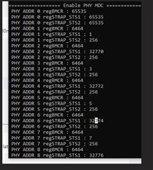
Sometimes at start-up, one or more of the links are not connected and once we try to read the ID of the PHY, we read all the register from the PHYs  FFFF . We tried to disable and enable the PHY (using the power down pins) that are not working properly and we see the issue is still there, and  a power cycle will often solve the issue (and we can read correct data from PHY again). 

Can you please tell us which possible scenarios may block the PHYs and lead to read FFF from MDIO ?

We investigate the issue further, and we have some remarks may help you to give some feedback to us. 

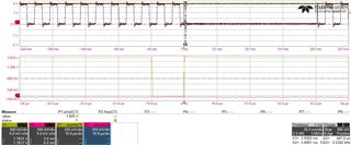
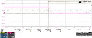
1-) We use the 3 supply mode and we enable 1V8 and 2V5 supplies at the same time. But 1V8 reaches the operational minimum limit of the PHY (1.71V) around 70us earlier than 2V5 operational minimum range(2.375).

2-) We give no reset to PHY from the FPGA and reset signal is pulled up with 1V8 rail which is IO Voltage level. 

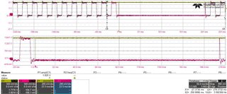
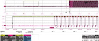
3-) I also see there is a power down requirement which says When powering down the DP83867, the 1.8-V supply should be brought down before the 2.5-V supply. Brought down means out of the operational limits or down to 0V or something else? 

Pictures are power-up and power down scenarios of 1V8 and 2V5. If you cant see the pictures clearly, I can send an e-mail.

If you think some other measurements may help to investigate more, please let us know.

Best regards,

Onur Kusakoglu

  • Hello Onur,

    Can you please check RX_CLK signal and report back for working and non-working (needing a reset) cases?

    In addition, what speed of SMI are you operating at? Would it be possible to slow this down to 1kHz as it seems that there are a lot of devices on the bus.

    On that same note, does reducing the amount of PHYs on the bus improve matters?

    Regarding question 3, power down to 0V.

    Sincerely,

    Gerome

  • Good morning,

    Thanks for the fast response,

    Power down to 0V is according to datasheet information.

    You haven't commented on power up sequence and reset questions which are my question-1 and question-2. 

    I will check RX clock when it is working and when it is not working. 

    MDC clock rate is 2.5Mhz, and 10Phy chain or 5 Phy chain does not make any noticeable difference. We sometimes see issue on one and sometimes on the other. 

    This is 1Gbps application and 10 PHYs have RGMII interface and 10 PHYs have SGMII interface. But sometimes (once in a while) we have problems reading PHY registers at start-up and only solution to enable the PHY is a power cycle. (By default PHYs are in power down mode with a pull down resistor)

    Let me know if you have further questions. 

    Best regards,

    Onur

  • Hello,

    I am not sure what you mean by question 2. What are you asking when it comes to the reset?

    Regarding question 1, it would be ideal if table 136 were followed in datasheet. 

    If you remove 1.8V power, as power up PHY is 2 supply mode, is this behavior still seen?

    Sincerely,

    Gerome

  • Dear Gerome,

    First of all I would like to think for the quick response, second of all I would like to add some remark to save you time.

    currently our design use an FPGA which is used to control the PDWN pins of the PHYs and the MDIO/MDC.

    the current power up sequence of the board include :

    - 2.5 and 1.8 V up.

    - the moment the FPGA bootup the MDC will be toggling for all the PHYs.

    - the PWDN is assert.

    after power up we wait at least 300 millisecond and the FPGA will do :

    - deassert the PWDN.

    - wait 300 milliseconds.

    - read the PHYs.

    My question now that I hope you can answer, is it possible that because the MDC is toggling during the power up sequence can lead to bloc the PHY ?

    currently when the issue occurs we read from MDIO FFFF. 

    do you suggest that we have to keep the MDC high or low during the power up sequence (at least 200 ms as mentioned in the datasheet)

    best regards

  • Hello,

    The current hypothesis within the team regarding this issue is that there may be too much capacitance due to many PHY on the line that it might be pushing the SMI timing out of spec. This is why we are suggesting to see if situations were improved at a slower speed as the parasitics would not be as involved.

    In addition, could you try and run another experiment where you only have one PHY on the MDC/MDIO bus line (disconnect the other PHYs from the line) and check to see if failure signature is still present. Then if not, add a PHY back in one-by-one checking if the signature appears after X number of PHYs have been added back into the line.

    Also, could you scope the MDC and MDIO lines with all PHYs on bus, as well as when one PHY is on bus? We are looking at the rise/fall time as well as the delay between signals.

    Sincerely,

    Gerome

  • Hi Gerome,

    thank for you for the reply, we thought so and we already scope the MDC/MDIO and we saw that we have 40 ns as hold and 360 ns at setup.

    we already slow down the MDC to 2.5 MHz.

    Best regards.

  • I forgot to mention that we have 10 PHYs as RGMI working correctly, we have issue only with 5 PHYs configured as SGMI and shared the MDC/MDIO.

  • Hello,

    Just to confirm, the only failing behavior is the PHY is not-responsive to SMI?

    In addition, would a slower speed work (1kHz instead of 2.5MHz)? And if you were to separate this bus between RGMII and SGMII, would all the SGMII's work independently?

    In addition, in a non-working case, would resetting the PHY help?

    Sincerely,

    Gerome

  • currently we have 5 PHYs that are configure to have address 0x01,x02.... and they share the MDC/MDIO and we see sometime that after the power up  we try to read data from PHY we got always FF, this is why I suspecting that the failing PHYs get configured with default address 0x00 and this is why we read FF because we don't have any PHYs with this address.

    and to solve the issue I tried to use the hardware reset (stop MDC, assert reset wait 2 us, deassert the reset wait 2 us enable clock wait 100 ms (is more than 32 clock cycle) read the PHY but still we got FF.

    the only way to solve the issue is power cycle the board.

    best regards

  • Hello,

    Could you try probing the strap pins for address to ensure that during POR and reset that it is being strapped at the appropriate voltages?

    In addition, to confirm that the PHY is strapping in a different addresses, could you try and search for the PHY in the address range until it pops up?

    Sincerely,

    Gerome

  • Good afternoon,

    Voltages are okay.

    Phy is supposed to be at address 1, we checked address 0(default) address 1 and 2 but we couldn't reach it. 

    We gave a hard reset to reset_n pin(10us) to re-configure the PHY but it didnt work either. 


    MDC was disabled for more than 200ms after releasing the reset.

    Power-up signal behavior of reset signal and MDC.

    Do you see anything wrong?

    Best regards

  • Hello,

    There are 32 (0-31) different addresses. Could you please check all of them to confirm that the PHY has been strapped in a different address?

    Sincerely,

    Gerome

  • Hi,

    We can check the addresses, what would happen if we see it at a different address? We are already focusing on the latching of this strap resistors and did above measurements. Could you please let us know if those measurements seem okay?

    Best regards,

    Onur

  • Hi Onur,

    This is to confirm that PHY is jumping addresses as a failure signature rather than actually being at the same address but something else is taking it offline. Will check back regarding scope captures.

    Sincerely,

    Gerome

  • Hi Gerome, 

    as you may know that we have 5 PHYs shared the same MDC/MDIO and we are using the strap to set the address for each PHY.

    our configuration normally set this PHYs as address 1, 2, 3, 4 and 5. 

    Today we did some investigations that after the power up we enable the MDC and we try to access the register MBCR (0x00) for all the possible address (0 to 31). and we found out that sometimes we read 0xFFFF from the existing PHYs address and also we found that we could read the right value from other address that normally we don't have in our configuration with straps.

    also, after the reading all the possible PHYs we apply a hardware reset (stop MDC, assert the reset of each phy for more 1 us, deassert the reset and wait for 210 us, enable the clock and wait 2 MS) and read again the MBCR from all the possible PHYs but unfortunately sometime the reset does not solve issue because we read FFFF from some of working PHYs before the reset and vis-versa.

    best regards. 

  • Hello,

    So this does confirm that PHY is being strapped into a different address. During reset, can you probe to ensure that there is no traffic on RX_D0 and RX_D2 when reset and powerup? This very crucial as the only voltage that should be driving this node is from the voltage divider at the time of reset and power up. If there is traffic on the nodes during this time, this may cause the PHY to strap at a different address value. These pins are used for SGMII so there is a very likely chance this could be causing your issue.

    Sincerely,

    Gerome

  • Hi Gerome,

    we controlling the PWDN, RESET_N, MDC and MDIO buy FPGA, can you please tell me which signal shall I assert (high or low) to make sure that the RX_D0 and RX_D2 never have any traffic during the reset sequence ?

    btw, we have also 10 PHY as RGMII and after the power up we read from them FFFF too.

    Best regards

  • Hello Brahim,

    I would think that the traffic would have to stop from a higher level, ie MAC standpoint. The PHY will just pass whatever is given to them from PHY (Link Partner) to MAC or vise versa. This is also applicable for RGMII as well since they use these pins. 

    You should also check the bootstrap register 0x6E, 0x6F to see if anything else changed from your desired state during normal operation and also when the PHY jumped addresses.

    Sincerely,

    Gerome

  • Hi Gerome,

    First of all, thank you very much for your quick replies.

    RX_D0 and RX_D2 are only connected to strap resistor.

  • Thank you Gerome, 

    as Onur mention the RX-D0 and RX-D2 are connected only the strap we see the issue also when no partner is connected, which means that the PHY will never received data from the other partner and imply that no traffic in the lines right ?

    best regards

  • Hi Brahim,

    I would like to step back and reclarify what the problem statement is to my understanding:

    PHY is jumping addresses. This has been proven during issue condition where customer does not see PHY at intended address and then searches all 31 other possible addresses to find it. This is seen on RGMII and SGMII boards. Reset can sometimes help in both boards, but power cycling is the only definitive way to fix issue.

    Does this seem accurate? Or am I missing more details? If so, please clarify.

    When you mean partner, do you mean MDI link partner, or MII MAC?

  • I meant by partner is that we don't connect the RJ45 cable, we have seen too that sometime we need really to power cycle the board to solve the issue.

    but we would like to know what is the root cause of the issue.

    for example, after the power up we are able to read the MBCR reg from using the right address of the PHY but the moment we apply a reset hardware we read 0xFFFF which means that PHY did not strap correctly the configuration.

  • Hi Gerome,

    today we check the Strap of RX_D0 and we saw that when the reset is active the voltage is around the right mode but after releasing the reset, the RD_D0 goes to zero after 40 ns (in my understanding that it is moment that the PHY switch the pin to output) but according to the datasheet normally the RX-D0 remains input at least 120 ns (T2 ) + 64 ns (T3).

    is it normal that the RX-D0 goes to output configuration in such a short time (40 ns) ?

    Best regards

  • Hello, 

    This seems normal as it is a nominal measurement.

    Could you report out what the voltage is on the strap pins when you reset and it straps into the correct address vs when you reset and it straps into the undesired address?

    In addition, could you report back the register values of 0x6E and 0x6F when in the correct and incorrect modes? Ensure that for S and R devices that there is no network traffic at the time of reset to ensure that device is not seeing an unintentional voltage on the node outside of the voltage divider circuitry.

    Sincerely,

    Gerome

  • Hi Gerome,

    thank you for the quick reply, I will do the test tomorrow and I will let update about the outcoming of the result

  • Hi Gerome, 

    We still see the wrong address latching once in a while. Here is a screen shot of what we read. 

    We couldn't catch a non working latching pin but here is also a picture of latching voltage-reset relationship from the scope to set the address 10.

    Let me know if you need any other information.

  • Hi Onur,

    Are those reading in hex? If they are in decimal, could I ask if they could possibly be converted to hex for better debugging.

    Sincerely,

    Gerome

  • Hi Gerome ,

    actually they decimal and here in this picture they are strap correctly, but the PHY is not strapped correctly I will read FFFF which make sense because I will try to read PHY with an address that does not exist.

    I heard from my colleague that because the GTX_CLK may add some cross talking which make the PHY get wrong strap.

    is it recommended to stop the GTX_CLK during the reset sequence or is not necessary. 

    best regards

  • Hi Brahim,

    It is recommended that any traffic from MAC be stopped during reset sequence to avoid strapping issues.

    Sincerely,

    Gerome

  • Hi Gerome,

    We disable the whole traffic and we haven't seen any addressing issue since then. We will do regressions tests after XMAS holidays. 

    Thank you for your help and have a nice XMAS.

    Onur