This thread has been locked.

If you have a related question, please click the "Ask a related question" button in the top right corner. The newly created question will be automatically linked to this question.

PCA9538: Device not initializing to power-on default register values

Part Number: PCA9538
Other Parts Discussed in Thread: TCA9538

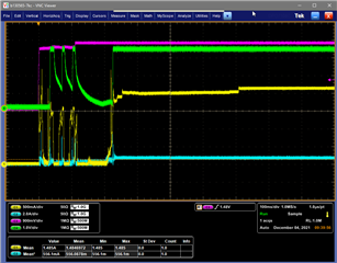
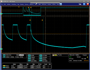
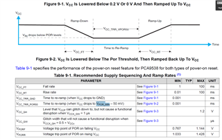
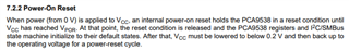
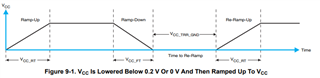
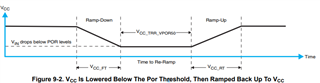
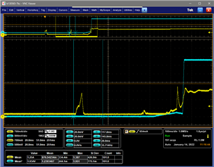
We are seeing a relatively small temperature around 50C where the PCA9538 device does not initialize to the proper reset default register values.  In this design, the RESET is tied high to 3.3V VCC through a 10k pullup.  We do see the 3.3V cycle on and off several times prior to the final power on resulting in the bad register defaults.  I'll attach a scope shot of this, but the during the last power-off cycle before the final power-on, the voltage does look to go comfortably below the 0.767 Vporf threshold, so I believe is meeting all the specs for a good POR. (green trace in scope plot)

For other debugging, we have wired in a system reset to the PCA's reset pin, which goes high roughly 250 ms after power on, which resolves the bad POR register values.  We also modified a couple of units to resolve the power on/off cycling during turn on, which also resolved the bad POR register values.

Given those successful trials, I believe that the POR circuit on the device is not working properly for this particular power-on condition, but it isn't clear that the power is violating the data sheet power-on specifications.  Hoping you can validate that the Vcc waveform captured can cause a POR circuit disruption and/or clarify if there is a device specification we are violating with that Vcc waveform.

Thanks - Eric

  • Hi Eric,

    May I have a bit more clarifications on the scope captures and what each color represents? Do any of the traces represent the voltage on the /RESET pin? 

    This device does have a /RESET errata in listed in section 7.2.2.1. It might be possible that at times VCC < /RESET. In this case, current will flow from /RESET pin to VCC pin causing VCC to be pulled above its regular voltage level. This might affect the way the POR circuit is operating. 

    I have also notified an I2C expert about this question. In the mean time, can you provide more clarification about your scope captures? If you have a schematic of the PCA9538 readily available, this will help to expedite a solution. 

    Regards,

    Tyler

  • Hi - for this design, /RESET is just pulled up to Vcc - so using the internal POR circuit to properly initialize the registers.  The scope shot has the PCA9538 Vcc rail in Green during the power-on.  The other traces are signals not connected to the PCA9538 device.  Based on testing since the initial post, I need to clarify what we are seeing.  The PCA device is failing to initialize to the default register values in a small temperature window, about a 5C window that falls somewhere between 50C and 70C.  For the rest of the -40 to +70C product temperature range, the device initializes registers to the expected values.  We have observed this odd behavior all 7 units tested so far - the failure temperatures are consistent on a given unit, but vary from unit to unit over the 50-70C range mentioned.

    After the bad init, we are able to read and write the registers to their correct power-on values using I2C on all 7 units tested.  With the latest test code, the I2C access where we read/verify the PCA register values is the first I2C access performed after power-on.  

    Thanks - Eric

  • Hi Eric,

    Let me discuss this problem with our I2C expert. I will get a response to you by tomorrow by around 4pm CST.

    Thanks,

    Regards,

    Tyler

  • Clearer capture of PCA9538 Vcc during startup resulting in corrupted default register values.  The first 3 power-up/decay cycles are inadvertent and I don't expect the PCA9538 to work at any time during those.  The last Vcc ramp and held on (right edge of the zoom) is the one that we read the bad init register values - maybe 5 sec after power-on.  Note - the initial power up/down cycles happen on boots where the registers init properly too - really nothing obviously different between this one and one that works at about 5C cooler temperature.

  • Hi Eric, 

    Thank you for this extra information and scope capture. I still don't have a clear direction on what this problem might be. 

    I am meeting this afternoon with our I2C expert. I might need another day to develop a response. 

    In the mean time, do you have a schematic on hand?

    Regards,

    Tyler

  • Hi Eric,

    I was able to talk to our I2C expert about this matter. What I gathered from the short meeting was the following:

    PCA9538 have had issues in the past with power-on-reset circuitry that the TCA variants fixed. If you want a p2p compatible replacement for this device, the TCA9538 would be your best option.

    Implementing a bleeder resistor of 50k to 100k might be of help to discharge VCC to GND on the device to make sure that the power level falls below the 0.2V threshold (more ideally pulled to GND) before being powered up to VCC again to reset default register values. This solution doesn't help for a system that is battery powered, because you will have bad power consumption over time. If you always have a supply constantly powering the system, this might be a viable option. 

    I noticed in the above oscilloscope capture that the VCC level is around 250mV to 300mV before being powered up to 3.3V. Is it possible to pull this level to GND before powering up the device back up to VCC? This will give the best operating conditions for resetting to default register values. 

    Regards,

    Tyler

  • Thanks - are you saying it is known that the Vcc level not going all the way to GND is a potential problem for the PCA9538 part?  There was a section specifically about that in the data sheet that indicated going below Vpor_min was sufficient, although that voltage isn't actually specified anywhere in the data sheet.  I had been assuming it was 50mV from the lowest Vpor threshold of 0.767, which let me to believe the waveform was ok.  I might be able to run a test to verify the residual voltage before the final power-on is the problem - let me see what I can pull together.  On your end, can you verify that the data sheet section I copied below isn't actually sufficient to guarantee correct power-on default register values?

  • Hi Eric,

    I was reading about this information on section 7.2.2 of the PCA9538 datasheet. 

    This section claims that powering up from 0V to VCC, registers and state machine will reset to their default states after crossing the VPOR threshold. 

    Section 7.2.2 seems to match up with Figure 9-1 when VCC is lowered below 0.2V or 0V and then ramped back up to VCC. 

    This 1st power-on-reset is when the device is first powered on from 0V.

    The second power-on-reset is what you are concerned with. When you exist at a voltage VCC, drop below VPORF, and then ramp back up to VCC. This is considered the second version of POR as depicted in figure 9-2.

    All the timing requirements seem to be met in your scope captures. You are going well below the 767mV threshold for a successful power-on-reset. According to my discussion with our I2C expert, has had issues in the past with PCA9538 POR circuitry that the TCA9538 fixed. 

    I suggest pulling VCC all the way to GND before powering back up to VCC to ensure that you are well below the threshold. Please let me know if this fixes the register/state machine reset issue you are facing.

    Regards,

    Tyler

  • Thanks - ran another test where we were able to prevent those initial 2 or 3 power-up/down cycles (so Vcc just stays low prior to the main ON ramp) and the device is initializing correctly.  I'll have to review our options, sounds like switching to a TCA9538 could work, or making this change that prevents the inadvertent early power-on cycles may fix the issue also.  Thanks for your help.  

    Green trace is working 3.3V in the previous problem temperature range.  Yellow is unrelated current trace...