This thread has been locked.

If you have a related question, please click the "Ask a related question" button in the top right corner. The newly created question will be automatically linked to this question.

SN65HVD70: Kindly advise on Termination Resistor required or not?

Part Number: SN65HVD70
Other Parts Discussed in Thread: SN65HVD73, THVD1410

Hi,

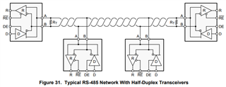
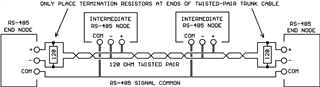
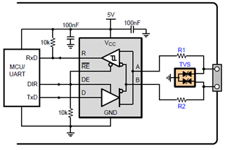
We are using RS485 SN65HVD70, My doubt is, when the Termination resistor(Rt) and Bias resistor's are mandatory or optional ?

We read document TIA/EIA-485 (RS-485), SLLA036D and https://e2e.ti.com/blogs_/b/analogwire/posts/rs-485-basics-when-termination-is-necessary-and-how-to-do-it-properly.

But still having some doubt on the calculation.

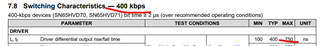
1. If, 2tpd > tt/5, we need to use Rt and if 2tpd < tt/5, no need to use Rt right?

2. How to find propagation time tpd?

3. unit interval (UI) mean (T=1/F) and F is Transmit date speed that is baud rate right? If buad rate is 9600 bit/sec, UI=1/9600=0.000104 right?

4. Finally, unable to relate with equation 2tpd > tt/5. Kindly advise how to calculate tpd and tt with giving one example. We use buad rate= 9600 bit/sec and cable length 100meter.

Thanks and regards,

Naveen K


Thanks and regards,

Naveen K

  • Naveen,

    1. Correct. However proper termination is always suggested except there is any special reason.

    2. tpd is the propagation time of the cable, which is roughly 5ns/meter. 

    Network Propagation Delay Calculation and Testing | Flukenetworks

    3. Correct.

    4. tt is the rise time of the transceiver, for example, 750ns of SN65HVD70. 2tpd > tt/5 => tpd>75ns (about 15 meter). 

    Regards,

  • Hi Hao,

    Thank you for the information.

    Regarding to tpd is well understood. tpd will be 5x500=2500ns for cable length 500meter.

    1. But for tt still having some doubt. you have taken 750ns from the SN65HVD70 datasheet right? so, we need to refer max value of "Differential output rise/fall time" in the datasheets for any other partnumber, right?

    2. In, SLLA036D document, "the driver output transition time can be no more than 0.3 times the unit interval (UI)", 

     tt ≤ 0.3 × UI  => tt ≤ 0.3 (1/500000)  =>  tt ≤ 600ns for 500kbps,  if baud rate=9600bps tt ≤ 31250.

    In equation "tt ≤ 0.3 × UI", "0.3" is fixed for all the conditions like any IC/baud rate/ cable length/application or it may vary

    3. We have to refer case 1 or case 2 method for tt calculation? example: 750ns (case1) or 600ns (case2) here?

    4. If our application, baud rate is 9600bps, cable length 500meter, tpd will be 2500ns, but how much will be the tt ? what is the value on final equation "2tpd > tt/5"?

    Thanks and regards,

    Naveen K

  • Naveen,

    1. Yes, I quoted the max tr/tf in the datasheet. 

    2. Yes. If 0.3 x UI is taken by the rise and fall time, the settled time for MCU to sample is only about 0.4 x UI.

    3. SN7565HVD70 works up to 400kbps. Therefore you may need another transceiver with faster rise/fall time for 500kbps applications.

    4. Again, tt is associated with the transceiver. You can choose proper ones for your applications.  

    Please let me know if you any further questions. 

    Regards,

  • Hi Hao,

    Thank you for the information.

    1.  We use SN65HVD73 and SN65HVD70 in one of the device and connect each other. Application Requirement is; Baud rate 9600bps, Cable length 500meter. For both part below calculation will be correct right?

    tt ≤ 0.3 × UI  => tt ≤ 0.3 (1/9600)  =>  tt ≤ 31250ns

    2tpd > tt/5  =>  2*(5ns*500) > 31250ns/5   =>  5000 > 6250

    2. For above calculation " 5000 > 6250", Termination resistor not required right? 

    3.To calculate tt, we have to use this equation "tt ≤ 0.3 × UI  => tt ≤ 0.3 (1/9600)  =>  tt ≤ 31250ns" or we need to consider the max value of tr/tf=750ns=tt ?

    because if we consider our application baud rate, tt=31250ns and if we consider max value of tr/tf in datasheet, tt=750ms. Which one we have to consider?

    Kindly advise, based on this i want to ask main question.

    Thanks and regards,

    Naveen K

  • Naveen,

    I'm sorry if I didn't make it clear. tt should be 750ns if you use SN65HVD70. 

    4. tt is the rise time of the transceiver, for example, 750ns of SN65HVD70. 2tpd > tt/5 => tpd>75ns (about 15 meter). 

    You can check out this app note for detailed discussion.

    https://www.ti.com/lit/an/snla027b/snla027b.pdf

    Figure 14, 15 and 16 give clear visualization. 

    May I know if there are any specific reasons you want to skip the termination?  

    However proper termination is always suggested except there is any special reason.

    Regards,

  • Hi Hao,

    Thank you for the information.

    We are having few products, will take two products for example. one is Gateway device and other one is Sensor, both having RS485.Number of RS485 devices and cable length will vary from one application to other. Baudrate will be 9600 bit per sec.

    1. In case1, one Gateway(Master) and one sensor(Slave) is present. Cable length 5meter, 25meter, 100meter

    2. In Case2, one Gateway(Master) and 5 sensor(Slave) is present. Cable length 5meter, 25meter, 100meter

    In some application, our Gateway/Sensors will be integrate with third arty RS485 devices/sensor

    1. In above all the cases, for any cable length Can we use Termination resistor. or not? 

    2. Even for small cable length and slower speed communication,  we can use termination resistor, right? it will be no issue right?

    3. Because, as per the datasheets, only 2 termination resistor should be connected in a entire node/loop. We don't know whether third-party devices having termination resistor or not inside the modules. Unknowingly if the number of termination resistors will be 3 or more  in the same node/loop, will work properly?   4. Good practice is to have the onboard Termination resistor or External through hole resistor on the connector?

    Thanks and regards,

    Naveen K

  • Hi Hao,

    Are you back from holiday's?

    Thanks and regards,

    Naveen K

  • Naveen,

    Thanks for checking in - Hao (along with much of our team) is out of office through the remainder of this calendar year and is returning by the second week of January. Thanks for your patience, and I hope your holiday season is treating you well.

    Best,

    Danny

  • Naveen,

    Happy new year! 

    1. Yes, you can use termination for both cases in your applications.

    2. Even with small cable length and low speed, it doesn't hurt to use termination. Again, termination are always recommended. 

    3. What would the maximum number of nodes come from 3rd party? 

    4. Both surface mount and through pole resistors should work. What's critical is that the resistance matches the cable impedance. 

    Regards,  

  • Hi Hao,

    Thank you for the information.

    "maximum number of nodes come from 3rd party" it's depends on applications. Maximum we connected is 5 RS-485 Devices interconnected.

    Main Agenda of this discussion: Kindly advise can we use Termination resistor for all the below cases?

    1. For Smaller cable Length or larger cable Length, ex: 0.5meter to 10meter. Need termination resistor?

    2.  For larger cable Length, ex: 10meter to 100meter.Need termination resistor?

    3. Only 2 RS485 devices connected with 2meter or 10meter cable, Ex: One Master and One Slave. Both Master and Slave need Termination Resistor?

    4. More than 5 RS485 Devices Connected  with 2meter or 10meter cable, All 5devices need termination resistor?

    I. All 5 RS-485 devices can have Termination resistor or only any two devices should have Termination resistor?

    II. If all 5 RS-485 devices have  120 Ohm Termination resistor, it will create 5 resistors in Parallel and makes 24Ohm equivalent resistor. It will fine or makes any malfunction? This is our main concern, we noticed in some reviews/documents.

    III. We have experienced while testing with 2meter cable length, 2 devices connected Master and Slave.

         a. Sensor is working fine without Termination resistor for 2meter and 10meter cable length.

          b. Receiving Garbage data from Energy meter for without Termination resistor. Receiving expected data for with Termination resistor.

    Thanks and regards,

    Naveen K

  • Naveen,

    For your questions 1 and 2, again as I mentioned before the calculation is based on the rise time of the specific device you choose. 

    3. Yes, RS-485 works best with daisy-chain topology, meaning one main bus with some short stubs.

    4. Given the maximum 3rd party nodes are 5, the worst case is that each node comes with termination resistor. The impact is like you said, the load of termination becomes heavy (24Ohm in total), which makes the bus amplitude smaller. However the RS-485 driver output is 1.5V min with 54Ohm load, while the receiver input threshold is 0.2V. With 5 termination resistor, you can check if the receiver input voltage of the farthest node is still much larger than 0.2V. 

    Can you elaborate this result?

    III. We have experienced while testing with 2meter cable length, 2 devices connected Master and Slave.

         a. Sensor is working fine without Termination resistor for 2meter and 10meter cable length.

          b. Receiving Garbage data from Energy meter for without Termination resistor. Receiving expected data for with Termination resistor.

    Do you mean without termination, one side of two nodes can receive data? 

    Regards,

  • Hi Hao,

    Regarding to calculation, "considering 9600 baud rate, Cable length upto 30meter".

    We have noticed below diagram one in THVD1410 datasheet and others in other Article.

    1. In diagram, only in end nodes Termination resistors has used and written that "Only place 120 ohm termination resistors at the ENDS of the RS-485 twisted-pair cable".

    That is why we are having bit confusion that, All 5 devices having termination resistor it will work or not?, As you said, we can connect Termination resistor to all the device end points. If 10 devices  connected we can use 10 Termination resistor on respective 10 end points. If 36 RS485 devices connected, then we need 36 Termination resistor on respective end point right? Why am confirming with more clarity that to avoid de-solder, if each RS485 device need Termination resistor, then i can add on PCB and avoid to connect externally.

    Thanks and regards,

    Naveen K

  • Termination resistors have the desired effect on the signal shape only at the two ends of the bus.

    Each resistor increases the load on the bus. Normal RS-485 transmitters are designed for only two resistors; more resistors will reduce the current through each resistor, which can make the voltage drop over the resistor too small for the receiver. If possible, add a mechanism to disconnect resistors (e.g., a jumper). Alternatively, do not place termination resistors at any receiver, and add separate termination devices (consisting of nothing but a resistor) at both ends.

    For slow speeds, you can use AC termination (see section 5 of AN-903).

  • Echoing Clemens' point, 2 termination are need for RS-485 system (mostly with daisy chain topology). Here is an app note for your reference (section 6).

    https://www.ti.com/lit/an/slla272d/slla272d.pdf

    I mentioned 5 termination because you said they're from 3rd party. With a small number of termination (>2), driver might still be able to drive the bus fine. In 'standard' RS-485 systems, you will only find 2 termination. 

    Regards,

  • Hi Clemens and Hao,

    Thank you for the information.

    From overall discussion i can consider/conclude that, Kindly confirm for individual query.

    1. Standard RS-485 system should have only 2 Termination resistor even if the Bus line connected with 2 devices or 32 devices, right?

    2. If Bus line connected with 32 devices and all 32 devices having Termination resistor (Total 32 resistors present in the Bus). This will also works fine?

    3. As Clemens suggested, we should avoid case 2 and disconnect 30 resistors and keep only 2 Termination resistor in 32 device Bus, right?

    4. Sometime, RS485 Bus will not work properly(Error like Garbage data) Without termination resistor even if the10meter cable length, 9600 Baudrate, right? 

    This conversation will help us to decide put onboard Termination or External Termination. Unable to give jumper option due to avoid user access (Enclosure already designed).

    Thanks and regards,

    Naveen K

  • 1. Yes.

    2. Probably not.

    3. Yes.

    4. At such a low speed, it might work. But you'd have to check with an oscilloscope how large the reflections are (at the ends and anywhere in the middle).

  • Hi Clemens,

    Thank you for the information and it will be helpful.

    1. Kindly confirm, Unknowingly(Third-party sensor/device may have built in onboard resistor), for How much maximum Termination resistors Bus will works fine? I hope, maximum 15 Termination resistor in a Bus may also works fine, right?

    We have connected our sensor board to our main board with normal wire's(not rs485/cat cable) length 0.5meter, 9600bps.

    Without Termination resistor, getting error/Garbage data_logs on the PC (Using Main boar UART-USB connected to PC to view logs)

    If we connect single resistor at any side either master or slave, getting expected fine data.

    2. We need to check with CAT or RS485 cable without resistor whether it will works or not for low speed with smaller distance?

    3. Our doubt is, may be normal cable/wires will not works?

    Thanks and regards,

    Naveen K

  • 1. Every additional resistor decreases the noise margin. Drivers are designed to generate at least 1.5 V over the termination resistors; receivers must be able to handle at most 200 mV. 15 resistors is probably too much current for the driver(s) and is unlikely to work.

    2. You have to measure. (Use an oscilloscope to check for reflections and other noise.)

    3. Other cables are likely to work. (If they do not use twisted pairs, you will get more noise.)

  • Hi Clemens,

    Thank you for the information.

    We will check for case 2 & 3.

    And one more thing, How about the Bias Resistor and this is also a mandatory in the bus line? If required, only one end should have bias resistor or 2 ends can have?

    TVS Diode will helpful for ESD protection right. Below diode spec will be fine or could you advise if any thing else?

    Voltage - Reverse Standoff (Typ)
    12V (Max)
    Voltage - Breakdown (Min)
    13.3V
    Voltage - Clamping (Max) @ Ipp
    26V,
    Power - Peak Pulse
    400W
    Capacitance @ Frequency
    75pF @ 1MHz

    Thanks and regards,

    Naveen K

  • Naveen,

    Bias network is not a must. Please refer to section 7 of this app note.

    https://www.ti.com/lit/an/slla272d/slla272d.pdf

    Working with -7V to 12V common mode, SM712 is popular TVS for RS-485 systems. 

    Regards,

  • Hi Hao,

    Thank you for the information.

    We will consider Bias resistor is not mandatory.

    1. If we use bias resistor for Failsafe, only one bias resistor should be present in a entire bus lines, right?

    2. If bus having Bias resistor, There is no drawbacks right?

    3. We have connected 3.3V to IC VCC pin. Pullup(On Bias) resistor should be connected to 3.3V or 5V or both will be fine ?

    4. Pulse resistor(R1,R2) is only to match the TVS diode clamp voltage and its a optional right? We are having 220 ohm Ferrite beads  instead Pulse resistor. It will be sufficient right?

    Thanks and regards,

    Naveen K

  • Naveen,

    1. yes;

    2. the drawback are constant DC current and less maximum bus nodes;

    3. It's better to connect the same rail as supply;

    4. yes. if the protection is sufficient depends on the system requirement. Resistors and TVS need to work together to achieve the protection rating. 

  • Hi Hao and Clemens,

    Thank you for your all the information and appreciate your support.

    Thanks and regards,

    Naveen K