


Part Number: TPS25750
Other Parts Discussed in Thread: TPS54JA20
Hello,
We are working on a project which has to be maintainable in the future and I have to provide solutions for the repair department based on diagnostics. We need to replicate conditions where a client messes up with the electronics (opens the case and touches circuits).
We did ESD discharge on 5 samples (simulating average human-circuit interaction) and we want to know if it's the IC that malfunctions or whether the passive components got blown.
However, we are new to using TPS25750 and it's different than MOSFETs.

Here is our circuit. In green is the USB-C line, in Yellow is the EEPROM flashed with 15V 3A configuration. On the right side in PINK is a converter from 15V to 5V.
On the bottom in blue/cyan are the consumers that operate on 5V from the converter.
This is our setup. Now we have the following behavior from the IC.
When connected to a passive 5V USB-C line, both the 5V line and the (internally converted by TPS25750) 3.3V line are stable. PPHV outputs 5V.
However, when we connect a 100W USB-C PD charger - all lines fluctuate including the CC line as you can see in the captures below. What is more, a soft clicking noise can be heard every time a peak is produced in the oscilloscope reading.
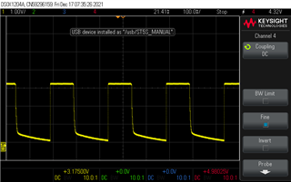
3V3
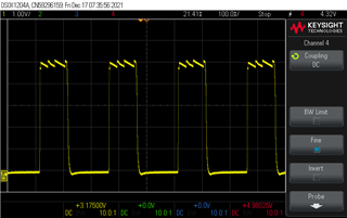
5V
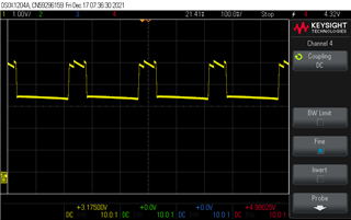
PPHV
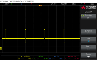
CC line
What we need to determine from this is whether the IC has been affected by the ESD or the passives around it (for example capacitors).
How do we do this? Do you recognize any of the listed behaviors?

