This thread has been locked.

If you have a related question, please click the "Ask a related question" button in the top right corner. The newly created question will be automatically linked to this question.

DS90UB914A-Q1: 914A flickering issue debug

Part Number: DS90UB914A-Q1

Hi Team,

There is a good new that we DIN DS90UB914A-Q1

And there have one thing need your support!

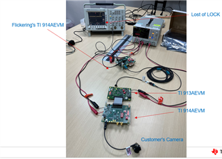
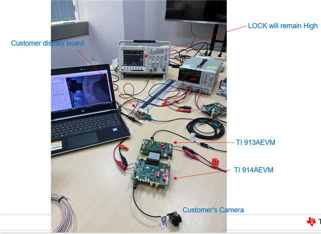
We have check customer’s oToCAM204 camera module & cable , It seems no fail in those test.

What else do we need to verify to prove the problem on the customer's system?

Do we have guideline of verifying the 913 end of the customer's system?

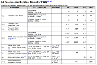
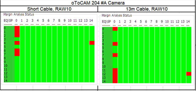
  1. Margin Analysis could meet spec
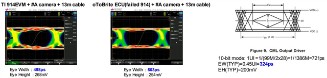
  2. 914 CML output and the EW/EH meets the criterial refer to datasheet
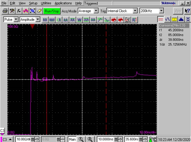
  3. Cable TDR measure within 50ꭥ±10%
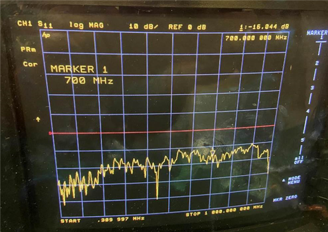
  4. Cable return loss at 700MHz is -16dB

Margin Analysis

914 CML output


TDR measure

Return loss

Thank you

  • Hello Kygo,

    I would recommend to verify the 913 camera design's RF parameters against the PCB side of the FPD channel specs. So you have already checked the cable, but the separately to the cable please check the IL/RL and TDR looking into the 913A board and share the results for review. See attached for guidance on how to measure these parameters:

    4118.FPD-Link Transmission Channel Test Procedure_ver1p2.pdf

    Best Regards,

    Casey 

  • Hi Casey

    Got it! THX

    And I have thought of the following test,

    Verify EVM with  914A connect oToCAM204 camera module & 914A EVM connect to 913 EVM will have or not flicking, please refer below table!

    But the difficulty is  what image data will be input to TI913A EVM with 99Mhz PIXCLK, How to do this rework? Please help tell me how to do it ,THX


    DES

    SER

    Result

    1.

    EVM with flickering 914A

    oToCAM204 camera module

    flickering

    2.

    EVM with flickering 914A

    913 EVM (but 913 change to oToCAM204 camera module’ 913 )

    Flickering or not

  • Hello Kygo,

    When the 914A output flickers, does this also correspond to a loss of lock? Or parity errors occurring in the 914A status registers? If so maybe you could use that to monitor the link instead of just checking for flicker. That way you could test the 913A EVM with 99MHz PCLK by just providing a PCLK input from a function generator or oscillator EVM to the 913A EVM to simulate the link rate. You wouldn't have the parallel data but that should not matter to just check lock and parity errors 

    Best Regards,

    Casey 

  • Hi Casey

    Yes ,when the 914A output flickers, and will have loss of lock.

     1.914A  RIN1+ pin to J5 have C6 & L9 in EVM, what is the purpose of this section of the circuit? Will it affect LOCK? Can I connect capacitors in parallel with the RIN1+ pin? Maybe I can partially compensate for the Lock signal from the circuit. THX

    2.What are the reasons that usually cause loss of lock?

    3.In addition to the RIN1+ pin, what other PIN layouts and SCH will affect the loss of lock


  • Hello Kygo,

    I'll need some additional time to look into this and get back to you. I'll plan to follow up next week after the holiday break 

    Best Regards,

    Casey 

  • Hi Casey

    Thank you for your help!

  • Ok Kygo,

    Here are the steps that I recommend taking here:

    1. Verify the total channel between SER/DES including cable, connector, and PCB. The measurements seem to only cover the cable portion of the link, but not the PCB. Usually if there is an SI issue in the design of either the 914A or 913A module, that would show up in the PCB, not the cable. I would suggest to get a TDR looking into the 913A board and then a measurement looking into the 914A board so we can see the impedance continuity at the connector interface first. Technically to get a total channel measurement the customer would need a probe station, but please have them start by getting TDR measurements looking into the SER and into the DES so we can see what the impedance continuity looks like. Use the edge rate of 150ps for the TDR measurement to match the typical rise/fall time of the DOUT CML driver 

    2. Verify the PCLK input jitter against the datasheet specifications in section 6.6 for the 913A module:

    Use the attached guide to match the correct scope settings for the measurement:

    7888.92x-91x Jitter_measurment_Sep2016.pdf

    Please provide those measurements and then we can help you review the results 

    Best Regards,

    Casey 

  • Hi Casey

    Thank you!

    1. Measure the TDR/S11 on oToBrite’s 913A board  & 914A board. It's within 50ꭥ±10%

    2.We did a comparison, using the customer's Camera (ISX019, PIXCLK 99MHz) to connect to TI 914AEVM, to generate Parallel data in BT601 format and PIXCLK, VS, LS input to TI 913AEVM, and then connect COAX cable (FPD-LINK III) with Flickering's TI 914A! You can still find lost of LOCK as shown in Figure 1

    And Figure 2 is to replace Flickering's TI914A with a 914-to-USB Display board from one of the customers, and its LOCK will remain High

    >>>Please help identify where this test needs to be improved? Can we discuss it with customer next Monday?

    Figure 1

    Figure 2 

  • Hello Kygo,

    I will take a look at this new info and provide a suggestion on how to proceed next week on Tuesday (Monday is a US holiday for TI)

    Best Regards,

    Casey 

  • Hi Casey

    Thank you! Looking forward to your reply.

    Happy new year !!!

  • Kygo,

    I'm confused on what the customer is trying to get from this activity. Are they trying to say that they have a faulty 914A unit? So they have populated that unit on a 914A EVM and they are using setup to propose that the 914A unit is faulty? 

    If so before we make that conclusion I would suggest to measure the input jitter to the 913A EVM in that setup coming from the upstream 913+914 chain. At the end of the day, this chain will only work across PVT conditions if the input jitter provided to the 913A EVM is within the datasheet specifications. Keep in mind that when you make these back to back chains of SER->DES->SER->DES there will be a low frequency jitter accumulation through the stages that means the second 913A will see more jitter than the first and then that will translate to more output jitter on the 913A side that will make tracking the signal more difficult for the 914A at the end. There is expected to be normal variation between units within the datasheet limits so it is not conclusive to say that because one failed and the other passed this means the unit is bad (unless of course everything is within datasheet limits including power supplies, input jitter, etc). 

    Attached in my previous post is a guide for measuring the jitter to 913A

    Best Regards,

    Casey 

  • Hi Casey

    Got it

    If ok , please reserve your time of 2022 1/19 5pm in Santa Clara! And I will host a call .

    We can discuss with the customer, because the customer has been in the project for a long time, we could take this opportunity to reach a consensus and plan the subsequent measurement items ,THX

  • Hello Kygo,

    I am out of office this afternoon through the rest of this week on PTO so I would suggest to run this discussion with the customer directly for now and report back the feedback to my questions from the last post. I will be back in office next week but no reason to delay getting answers to what the customer is really wanting out of this discussion and they can also capture jitter measurements in that time as I suggested

    Best Regards,

    Casey 

  • Hi Casey

    Sorry , I missed your message because of our different time zones!

    After talk with customer , they would like to discuss with you to reach a consensus and plan the subsequent measurement items ,THX

    Please reserve your time to join the meeting ! I have sent calendar to you ,THX

  • Hello Kygo,

    I am out of office today and tomorrow but will respond back to you ASAP next week 

    Best Regards,

    Casey 

  • Hello Kygo,

    I don't see your calendar invite. What day is that?

    Again, I was already clear about what the customer should check here: input jitter to the SER against the datasheet spec using the measurement guide I provided before so please do have them check that before any meeting or the time will not be productive 

    Best Regards,

    Casey