This thread has been locked.

If you have a related question, please click the "Ask a related question" button in the top right corner. The newly created question will be automatically linked to this question.

DS89C21: Short circuit problem

Part Number: DS89C21

Hi team,

I got a question from customer.

"Model: DS89C21TMX NOPB, when debugging, 5 feet were short circuited. The attached circuit diagram is for reference. Please analyze the reason.
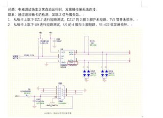
Problem: when the elevator runs automatically in express mode, it is found that the operator cannot be connected.
Phenomenon: through board monitoring, it is found that the Z signal pin is invalid.
1. short circuit test was taken DZ17 from on board, DZ17's 2 foot and 3 pin were not short circuited, and the TVS tube was not damaged.
2. short circuit test is taken U9 from on board, U9's 4 pin and 5 pin are short circuited, and RS-422 transceiver is damaged.

"

Thank you very much for your help.

Best regards,

  • Zhongui,

    I'm not sure what the question is here. Is the customer wanting to know what caused the damage, how to mitigate it, or something else?

    Regards,

    Eric Hackett 

  • Hi Eric,

    Thank you for your help.

    Yes,In short, the customer designed the above circuit diagram, but pin 5 is short circuited.,I hope to help analyze the cause.

    Thanks,

    Best regards,

  • Hello Zhongui,

    I have a couple suggestions. 

    My first suggestion would be to double check the input/output connections. Make sure that a transmitting line is not connected to another transmitting line. Pin 5 is a RS422 output signal from the device. Power-GND shorts could occur if Pin 5 RS422 output pulls HIGH while another driver on the same wire tries to pull low. This could stress the pin overtime and damage the device. 

    I looked at the datasheet for the SM712 TVS diodes and it looks like the reverse-standoff voltage (working peak reverse voltage) matches that of the common mode input voltage range for the RS422 standard: -7V to +12V. Since the communication distance is not long in the customer application, I do not see a common-mode potential being much of an issue. The clamping voltage of the SM712 may or may not protect the DS89C21 depending on the type of current surge seen at the inputs. Clamping voltages from Pin 1 or Pin 2 to Pin 3 is 19V and 31V. These values are both outside the abs. max receiver input voltage range of DS89C21 at +-14V. It makes sense that the device would fail first, and that the TVS tube is still intact. 

    If this system is already on the PCB, I would check all the solders to make sure that there are no solder shorts. Highly unlikely, but could also be a potential issue in the production of this application. 

    Regards,

    Tyler

  • This type of board has been in mass production, and the monthly shipment is about 10K, so the possibility of chip damage caused by the circuit itself is low.
    What factors and external factors can lead to 4-pin 5-pin short circuit for the chip?Can you list some possibilities?
    It would be best if the failed chip could be sent for sample failure analysis.
    Thank you very much
      Tom Dai  
    E-mail:daipp@stepelectric.com

  • Hi Tom,

    I misspoke in my previous response about RS422 standards. For some reason, I confused the RS485 voltage range with the RS422 voltage range. RS485 receiver input voltage range is -7V to +12V while RS422 receiver input voltage range is -10V to +10V. SM712 is a RS485 standard compliant device, not necessarily protecting voltage range of the RS422 standard. 

    Pin 5 on the DS89C21 is the RS422 signal output from the device. Its absolute maximum voltage is -0.5V to +7V. Since SM712 TVS diode reverse-standoff voltage is -7V to +12V, the DS89C21 will burn up before the SM712 device because it will allow -7V to +12V signals to pass through the device in the event of over-voltage. SM712 breakdown voltage range is -7.5V to +13.3V, in which the SM712 will draw significant current protecting downstream devices. Ultimately what I am saying is that the SM712 is not a viable protection device for this device. 

    With some quick research, I have come up with a short list of possible shorts on a manufactured PCB. 

    (1) Depending on tolerances and machine accuracy, a thin line of copper could remain causing a hairline short to be formed. 

    (2) Reflow soldering - Solder paste may accidentally connect two pins that are very close to each other. 

    (3) PCB Design - Traces may accidently be connected to different nets (a good program would catch this before a PCB is published, I highly doubt this would be the cause)

    (4) Solder Pads - If solder pads are large compared to the space between pads, you could easily form a solder bridge during reflow soldering processes.

    I will find out how to process the failed chip for a failure analysis report. I'll get this information to you as soon as possible. This process may take a bit of time to start due to the holidays.

    Regards,

    Tyler

  • Hi Tom/Zhongui,

    Failure analysis submissions can be found through this link on TI's website:

    https://www.ti.com/support-quality/additional-information/customer-returns.html

    If you did not buy the parts directly from TI, you will have to go through the customer return process through the distributer first: Digikey, Mouser, etc. 

    Regards,

    Tyler