This thread has been locked.

If you have a related question, please click the "Ask a related question" button in the top right corner. The newly created question will be automatically linked to this question.

TPIC8101: General setup questions and information

Part Number: TPIC8101

I designed in the TPIC8101 on my ECU for racing.  Now I would like to start programing it.  In all the datasheets/app notes it is a little unclear about does the "Integrator Time Constant" and "Gain" need to be calculated on the fly as the engine is running at different RPM.  I am assuming so but, all your references are static at 3ms (5000rpm on a V8) with a 50% integration time.  There is also no reference as to when the integration should start, at TDC, at 10degrees BTDC, I know it changes with every engine design but, there is no "in general" information which is what I am probably going to have to start with.  I am not even sure this will work on these engines which vary from 600hp to over 4000hp.  This is really for data collection and not control unless the data is clear that knock is definitely detectable.

Any help would be greatly appreciated,

Blest Regards,

Blake

  • Blake,

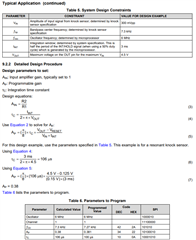
    Thanks for reaching out with your question.  In the datasheet application section there is a set of equations to help you determine the integrator time constant and gain.  These do not look like parameters you would need to adjust on the fly unless you are changing your int/hold signal from the microprocessor:

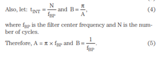
    The guide at this link (https://www.ti.com/lit/an/slyt580/slyt580.pdf) describes the integration time in a little more detail:

    So the integration time is the ratio of the number of cycles you wish to integrate (N) and the center frequency of the programmable bandpass filter.  Assuming you keep the integration time constant, you would end up with a different value for N as the motor speed changes.

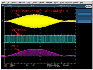
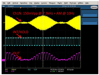
    You also asked about starting the integration.  I do not see any specific requirement for when this is to occur, but what will be important is that the integration time be consistent from pulse to pulse.  The device will integrate across the input for the entire time that the INT/HOLD pin is high.  Upon release the output with hold at the final voltage.  This behavior is demonstrated in the following reference design:

    https://www.ti.com/tool/TIDA-00152

    Here we see that the output integration creates an envelope representative of the knock event which can be tracked by the system.  

    Thanks,

    Scott

  • Scott,

    From what I can tell the INT/Hold pin timing would be changing with RPM.  From what I have read the INT period would be from TDC Top Dead Center of the piston to 40 degrees ATDC (After Top Dead Center).  So, from what you are saying it looks like the "Integrator Time Constant" and "Gain" will need to be calculated on the fly and updated when the INT/HOLD is low in between the cylinder firings.  All your examples show the data in steady state even though on this one the knock sensor input is varying.  I could not find any information in all the data sheets/ app notes that show a changing RPM.
    Thanks again for all your help,
    Best Regards,
    Blake
  • Blake,

    I suppose given that the base input frequency is changing, the filter center will need to be adjusted, which would impact the gain and period calculations.  Otherwise, with the varying number of cycles integrated, your baseline output level would be varying as well.  You're right, adjusting for the speed dynamically should help produce more consistent behavior for your tests.

    Thanks,

    Scott

  • Scott,

    Thanks, I will give it a try.

    Blake