This thread has been locked.

If you have a related question, please click the "Ask a related question" button in the top right corner. The newly created question will be automatically linked to this question.

THVD1520: Schematic review for THVD1520

Part Number: THVD1520

Hi team,

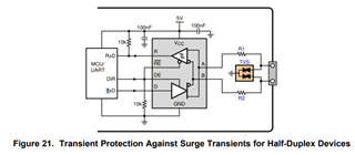
Can you help review the schematic of THVD1520?

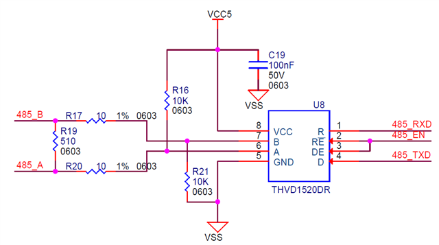
Also, I am not sure that whether the existence of R16 and R21 will influence the normal work. Seems that no pull-up/down resistors are utilized in reference design. Thanks.

Regards,

Xiaoying

  • R17/R20 typically are pulse-withstanding resistors. And if you care about surges, then you'd also add additional protection (see section 11 of the datasheet).

    R16/R21 are called fail-safe resistors; they ensure that the bus voltages are valid even when there is no active transmitter. They are weak enough so that they do not noticably affect the RS-485 signals.

    The THVD1520 has a fail-safe function that outputs a defined state even when the A/B voltages are invalid, so it does not need these resistors. You need them only if there is any receiver without fail-safe function on the bus, and then only at that receiver.

  • Hi Xiaoying,

    Similar to what Clemens already stated, external fail-safe resistors R16 and R21 are not needed due to fail-safe technology already implemented internally in the transceiver. The transceiver automatically outputs a known state when bus lines A & B are open circuited, short-circuited, or left idle. 

    R17 and R20 are pulse-proof resistors. These should be implemented if TVS clamping voltage is higher than the specified maximum voltage on the transceiver bus pins. Seeing no transient protection circuitry, I would recommend having transient protection device such as TVS on bus lines A & B to protect against high-voltage surges. I have attached figure 21. from the datasheet for your reference. 

    All other circuit connections look fine.

    Regards,

    Tyler